Extracted images: Dry Wells (Small-Scale GI)
Printed revision: March 2021.
Back to source | Original PDF | Image metadata
Original Mistral crops are preserved byte for byte. A crop can be a figure, table, equation, or other visual; no visual content is inferred as a numerical rule. Record and table associations use the same PDF page unless a direct image placeholder is identified. Nearby OCR excerpts are context, not verified captions.
PDF page 1, image 1
Mistral ID: img-0.jpeg. Extraction bundle(s): 2023_BMP_9_2_Dry_Wells. Original page | Image file
Tables on the same PDF page: Table 1
Surrounding OCR excerpt:
# 9.2 DRY WELLS

[OCR image]

Dry wells are subsurface stormwater facilities that are used to collect and temporarily store stormwater runoff generated by clean rooftops; runoff is discharged through infiltration into the subsoil. Dry wells may be used to comply with the groundwater recharge design and performance standard of the Stormwater Management rules. Additionally, they may also be used to reduce the volume of stormwater run
PDF page 3, image 1
Mistral ID: img-1.jpeg. Extraction bundle(s): 2023_BMP_9_2_Dry_Wells. Original page | Image file

Surrounding OCR excerpt:
# Applications

[OCR image]

Pursuant to N.J.A.C. 7:8-5.2(a)(2), the minimum design and performance standards for groundwater recharge, stormwater runoff quality and stormwater runoff quantity at N.J.A.C. 7:8- 5.4, 5.5 and 5.6 shall be met by incorporating green infrastructure in accordance with N.J.A.C. 7:8-5.3.

[OCR image]

Dry wells may be used to meet the groundwater recharge requirements of the Stormwater Manag
PDF page 3, image 2
Mistral ID: img-2.jpeg. Extraction bundle(s): 2023_BMP_9_2_Dry_Wells. Original page | Image file

Surrounding OCR excerpt:
s for groundwater recharge, stormwater runoff quality and stormwater runoff quantity at N.J.A.C. 7:8- 5.4, 5.5 and 5.6 shall be met by incorporating green infrastructure in accordance with N.J.A.C. 7:8-5.3.

[OCR image]

Dry wells may be used to meet the groundwater recharge requirements of the Stormwater Management rules. For more information on computing groundwater recharge, see Chapter 6: Groundwater Recharge.

# Design Criteria

## Basic Requirements

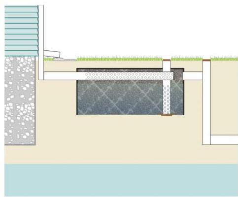
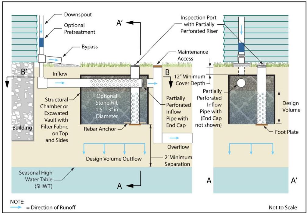
The following illustrations show the basic design criteria required for dry wells. The illustrations show possible configurations and flow paths and are not intended
PDF page 3, image 3
Mistral ID: img-3.jpeg. Extraction bundle(s): 2023_BMP_9_2_Dry_Wells. Original page | Image file
Surrounding OCR excerpt:
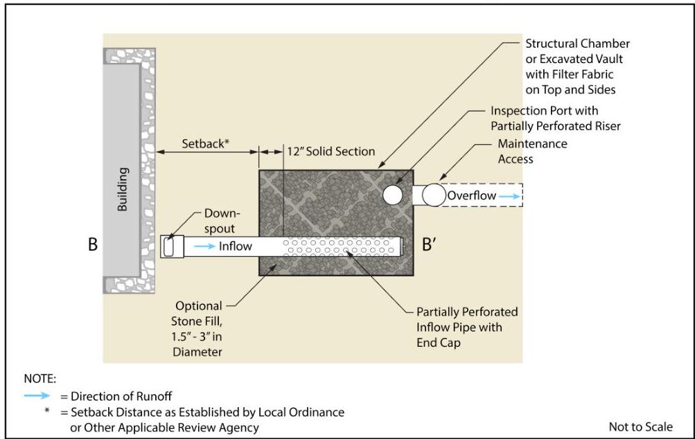
basic design criteria required for dry wells. The illustrations show possible configurations and flow paths and are not intended to limit the design. Additional information is provided on Pages 4 through 8.

[OCR image]
PDF page 4, image 1
Mistral ID: img-4.jpeg. Extraction bundle(s): 2023_BMP_9_2_Dry_Wells. Original page | Image file
Surrounding OCR excerpt:
# Dry Well Basic Requirements – Plan View Section through Inflow Pipe

[OCR image]

## Contributory Drainage Area

- The maximum contributory drainage area limitation is 1 acre, pursuant to N.J.A.C. 7:8-5.3(b).
- The entire contributory drainage area must be completely stabilized prior to use of the dry well.

## Inflow and Pretreatment

- The use of dry wells is limited to the collection of stormwater runoff generated by a clean roof that will not contribute nutrients, sediment or ot
PDF page 9, image 1
Mistral ID: img-5.jpeg. Extraction bundle(s): 2023_BMP_9_2_Dry_Wells. Original page | Image file
Surrounding OCR excerpt:
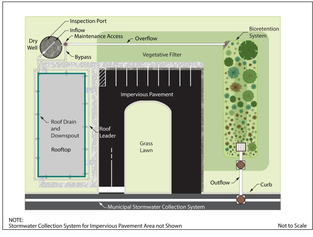
ining stone fill, that will meet the criteria for the stormwater runoff quality volume reduction if all of the rooftop runoff is directed to it, as shown in the illustration below.

## Example 1 - Plan View

[OCR image]

## Step 1: Runoff Calculations

Using the runoff calculation method described in the NRCS Methodology section of Chapter 5, the Water Quality Design Storm runoff volume from the 5,000 sf roof was calculated to be 431 cf. If site conditions allow, the anticipated volume reduction of this dry well is 431 cf.
PDF page 10, image 1
Mistral ID: img-6.jpeg. Extraction bundle(s): 2023_BMP_9_2_Dry_Wells. Original page | Image file
Surrounding OCR excerpt:
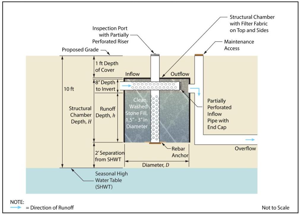
sions must be sufficient to contain, below the overflow, the entire volume of stormwater runoff generated by the roof by the WQDS. The following graphic illustrates key elements of the design for this site.

[OCR image]
Example 1 - Structural Chamber Dry Well Designed for Volume Reduction

In this example, the depth to the seasonal high water table is 10 feet. Assuming 1-foot depth of cover, the allowable structural chamber depth, $H$, is calculated as follows, excluding any thickness of the top of the structural chamber and the required filter fabric:

$$
\begin{array}{l}
H = SHWT\ Depth - (SHWT\ Separation + Cover) \