{"metadata": {"source_document": "NJ BMP", "version_year": "2021", "chapter_subchapter": "Chapter 9.2", "citation": "BMP 2021, Ch 9.2, p. 1", "topic": "Table 1"}, "programmatic_checks": {}, "content_markdown": "# Dry Wells (Small-Scale GI)\n\n## Table 1\n\n| N.J.A.C. 7:8 Stormwater Management Rules – Applicable Design and Performance Standards | | |\n| --- | --- | --- |\n| | Green Infrastructure | Yes |\n| | Stormwater Runoff Quantity | Not Allowed |\n| | Groundwater Recharge | Yes |\n| % | Stormwater Runoff Quality | Not Allowed |\n| Groundwater Recharge Mechanism and Corresponding Criteria | |\n| --- | --- |\n| Infiltration | |\n| Maximum Contributory Drainage Area | 1 acre |\n| Maximum Design Volume | Water Quality Design Storm Volume |\n| Maximum Drain Time | 72 hours, Using Slowest Design Permeability Rate |\n| Permeability Rate Factor of Safety | 2 |\n| Minimum Design Permeability Rate of the Subsoil | 0.5 inches/hour |\n| Maximum Design Permeability Rate | 10 inches/hour |\n| Soil Testing Consistent with Chapter 12: Soil Testing Criteria | Required |\n| Minimum Distance between Dry Well Bottom and Seasonal High Water Table | 2 feet |\n\nSource context and notes:\n\nSource revision: March 2021.\n\n# 9.2 DRY WELLS\n\n[Figure: img-0.jpeg (original PDF, p. 1)](SOURCE.pdf#page=1)\n\n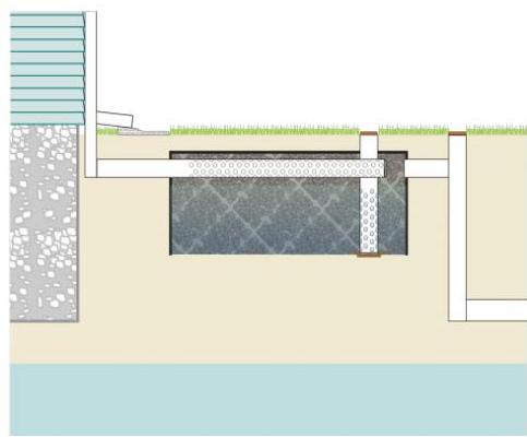\n\nDry wells are subsurface stormwater facilities that are used to collect and temporarily store stormwater runoff generated by clean rooftops; runoff is discharged through infiltration into the subsoil. Dry wells may be used to comply with the groundwater recharge design and performance standard of the Stormwater Management rules. Additionally, they may also be used to reduce the volume of stormwater runoff generated by a clean roof from the Water Quality Design Storm. Dry wells are assigned a 0% total suspended solids (TSS) removal rate.\n\n\n| N.J.A.C. 7:8 Stormwater Management Rules – Applicable Design and Performance Standards | | |\n| --- | --- | --- |\n| | Green Infrastructure | Yes |\n| | Stormwater Runoff Quantity | Not Allowed |\n| | Groundwater Recharge | Yes |\n| % | Stormwater Runoff Quality | Not Allowed |\n| Groundwater Recharge Mechanism and Corresponding Criteria | |\n| --- | --- |\n| Infiltration | |\n| Maximum Contributory Drainage Area | 1 acre |\n| Maximum Design Volume | Water Quality Design Storm Volume |\n| Maximum Drain Time | 72 hours, Using Slowest Design Permeability Rate |\n| Permeability Rate Factor of Safety | 2 |\n| Minimum Design Permeability Rate of the Subsoil | 0.5 inches/hour |\n| Maximum Design Permeability Rate | 10 inches/hour |\n| Soil Testing Consistent with Chapter 12: Soil Testing Criteria | Required |\n| Minimum Distance between Dry Well Bottom and Seasonal High Water Table | 2 feet |\n\n\n\n[Source PDF](SOURCE.pdf#page=1)\n\nOCR images on the cited PDF pages (page association only): [p. 1, image 1](images/page-0001-img-01.jpg)"}
{"metadata": {"source_document": "NJ BMP", "version_year": "2021", "chapter_subchapter": "Chapter 9.2", "citation": "BMP 2021, Ch 9.2, p. 11", "topic": "Table 2"}, "programmatic_checks": {}, "content_markdown": "# Dry Wells (Small-Scale GI)\n\n## Table 2\n\n| Inflow Area = 5,000 sf,100.00% Impervious, Inflow Depth = 1.03\" | | | |\n| --- | --- | --- | --- |\n| Inflow = 0.33 cfs @ 1.09 hrs, Volume= 431 cf | | | |\n| Outflow = 0.01 cfs @ 2.05 hrs, Volume= 431 cf, Atten= 98%, Lag= 57.3 min | | | |\n| Discarded = 0.01 cfs @ 0.60 hrs, Volume= 431 cf | | | |\n| Primary = 0.00 cfs @ 2.05 hrs, Volume= 0 cf | | | |\n| Routing by Stor-Ind method, Time Span= 0.00-58.00 hrs, dt= 0.05 hrs | | | |\n| Peak Elev= 6.33' @ 2.07 hrs Surf.Area= 154 sf Storage= 390 cf | | | |\n| Plug-Flow detention time= 464.3 min calculated for 431 cf (100% of inflow) | | | |\n| Center-of-Mass det. time= 464.7 min (535.0 - 70.3) | | | |\n| Volume | Invert | Avail.Storage | Storage Description |\n| #1 | 0.00' | 431 cf | 14.00'D x 7.00'H Vertical Cone/Cylinder
1,078 cf Overall x 40.0% Voids |\n| Device | Routing | Invert | Outlet Devices |\n| #1 | Discarded | 0.00' | 2.00 in/hr Exfiltration over Surface area |\n| #2 | Primary | 6.33' | 1.0\" Vert. Orifice/Grate X 12.00 columns
X 4 rows with 1.0\" cc spacing C= 0.600 |\n| Discarded OutFlow Max=0.01 cfs @ 0.60 hrs HW=0.07\" (Free Discharge)
+1=Exfiltration (Exfiltration Controls 0.01 cfs) | | | |\n| Primary OutFlow Max=0.00 cfs @ 2.05 hrs HW=6.33\" (Free Discharge)
+2=Orifice/Grate (Orifice Controls 0.00 cfs @ 0.02 fps) | | | |\n\nSource context and notes:\n\n# Dry Wells (Small-Scale GI)\n\nSource revision: March 2021.\n\nperformed using hydraulic and hydrologic modeling software, and it was determined that the diameter of the structural chamber required is 14 ft. The highest water depth produced by the WQDS is 6.32 ft, which is less than the maximum depth limit of 6.33 ft. The results are shown below.\n\n## WQDS Routing Summary Report\n\n\n| Inflow Area = 5,000 sf,100.00% Impervious, Inflow Depth = 1.03\" | | | |\n| --- | --- | --- | --- |\n| Inflow = 0.33 cfs @ 1.09 hrs, Volume= 431 cf | | | |\n| Outflow = 0.01 cfs @ 2.05 hrs, Volume= 431 cf, Atten= 98%, Lag= 57.3 min | | | |\n| Discarded = 0.01 cfs @ 0.60 hrs, Volume= 431 cf | | | |\n| Primary = 0.00 cfs @ 2.05 hrs, Volume= 0 cf | | | |\n| Routing by Stor-Ind method, Time Span= 0.00-58.00 hrs, dt= 0.05 hrs | | | |\n| Peak Elev= 6.33' @ 2.07 hrs Surf.Area= 154 sf Storage= 390 cf | | | |\n| Plug-Flow detention time= 464.3 min calculated for 431 cf (100% of inflow) | | | |\n| Center-of-Mass det. time= 464.7 min (535.0 - 70.3) | | | |\n| Volume | Invert | Avail.Storage | Storage Description |\n| #1 | 0.00' | 431 cf | 14.00'D x 7.00'H Vertical Cone/Cylinder
1,078 cf Overall x 40.0% Voids |\n| Device | Routing | Invert | Outlet Devices |\n| #1 | Discarded | 0.00' | 2.00 in/hr Exfiltration over Surface area |\n| #2 | Primary | 6.33' | 1.0\" Vert. Orifice/Grate X 12.00 columns
X 4 rows with 1.0\" cc spacing C= 0.600 |\n| Discarded OutFlow Max=0.01 cfs @ 0.60 hrs HW=0.07\" (Free Discharge)
+1=Exfiltration (Exfiltration Controls 0.01 cfs) | | | |\n| Primary OutFlow Max=0.00 cfs @ 2.05 hrs HW=6.33\" (Free Discharge)
+2=Orifice/Grate (Orifice Controls 0.00 cfs @ 0.02 fps) | | | |\n\n\nSource: HydroCAD® Summary Report; HydroCAD is a registered trademark of HydroCAD Software Solutions LLC. Used with permission.\n\n## WQDS Water Depth and Flow\n\n### Rate Routing Report\n\n[Source PDF](SOURCE.pdf#page=11)"}
{"metadata": {"source_document": "NJ BMP", "version_year": "2021", "chapter_subchapter": "Chapter 9.2", "citation": "BMP 2021, Ch 9.2, p. 11", "topic": "Table 3"}, "programmatic_checks": {}, "content_markdown": "# Dry Wells (Small-Scale GI)\n\n## Table 3\n\n| Time (hours) | Elevation (feet) | Discarded (cfs) | Primary (cfs) |\n| --- | --- | --- | --- |\n| 0.00 | 0.00 | 0.00 | 0.00 |\n| 1.00 | 1.24 | 0.01 | 0.00 |\n| 2.00 | 6.32 | 0.01 | 0.00 |\n| 3.00 | 5.97 | 0.01 | 0.00 |\n| 4.00 | 5.55 | 0.01 | 0.00 |\n| 5.00 | 5.13 | 0.01 | 0.00 |\n| 6.00 | 4.72 | 0.01 | 0.00 |\n| 7.00 | 4.30 | 0.01 | 0.00 |\n| 8.00 | 3.88 | 0.01 | 0.00 |\n\nSource context and notes:\n\n| Primary OutFlow Max=0.00 cfs @ 2.05 hrs HW=6.33\" (Free Discharge)
+2=Orifice/Grate (Orifice Controls 0.00 cfs @ 0.02 fps) | | | |\n\nSource: HydroCAD® Summary Report; HydroCAD is a registered trademark of HydroCAD Software Solutions LLC. Used with permission.\n\n## WQDS Water Depth and Flow\n\n### Rate Routing Report\n\n\n| Time (hours) | Elevation (feet) | Discarded (cfs) | Primary (cfs) |\n| --- | --- | --- | --- |\n| 0.00 | 0.00 | 0.00 | 0.00 |\n| 1.00 | 1.24 | 0.01 | 0.00 |\n| 2.00 | 6.32 | 0.01 | 0.00 |\n| 3.00 | 5.97 | 0.01 | 0.00 |\n| 4.00 | 5.55 | 0.01 | 0.00 |\n| 5.00 | 5.13 | 0.01 | 0.00 |\n| 6.00 | 4.72 | 0.01 | 0.00 |\n| 7.00 | 4.30 | 0.01 | 0.00 |\n| 8.00 | 3.88 | 0.01 | 0.00 |\n\n\nSource: HydroCAD® Routing Report; HydroCAD is a registered trademark of HydroCAD Software Solutions LLC. Used with permission.\n\nA structural chamber 7 feet in depth and 14 feet in diameter will provide sufficient volume to contain the WQDS volume below the invert of the overflow.\n\n[Source PDF](SOURCE.pdf#page=11)"}