Extracted images: Pervious Paving Systems (Small-Scale GI)
Printed revision: March 2021.
Back to source | Original PDF | Image metadata
Original Mistral crops are preserved byte for byte. A crop can be a figure, table, equation, or other visual; no visual content is inferred as a numerical rule. Record and table associations use the same PDF page unless a direct image placeholder is identified. Nearby OCR excerpts are context, not verified captions.
PDF page 1, image 1
Mistral ID: img-0.jpeg. Extraction bundle(s): 2023_BMP_9_6_Pervious_Paving_Systems. Original page | Image file
Tables on the same PDF page: Table 1
Surrounding OCR excerpt:
# 9.6 PERVIOUS PAVING SYSTEMS

[OCR image]

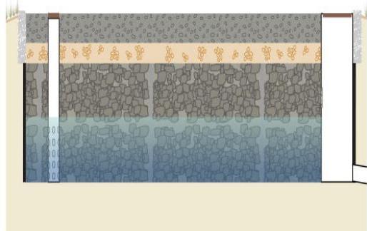
A pervious paving system is a stormwater management facility used to address the impacts of land development. The system consists of a durable, permeable surface course, which allows stormwater runoff to move through it; this surface course is placed over a transition layer and a storage bed of open-graded, i.e., devoid of fine particles, aggregate. There are two types: underdrained systems and systems
PDF page 3, image 1
Mistral ID: img-1.jpeg. Extraction bundle(s): 2023_BMP_9_6_Pervious_Paving_Systems. Original page | Image file

Surrounding OCR excerpt:
# Applications

[OCR image]

Pursuant to N.J.A.C. 7:8-5.2(a)(2), the minimum design and performance standards for groundwater recharge, stormwater runoff quality and stormwater runoff quantity at N.J.A.C. 7:8- 5.4, 5.5 and 5.6 shall be met by incorporating green infrastructure in accordance with N.J.A.C. 7:8-5.3.

[OCR image]

Previous paving systems may be designed to convey storm events larger than the Water Qualit
PDF page 3, image 2
Mistral ID: img-2.jpeg. Extraction bundle(s): 2023_BMP_9_6_Pervious_Paving_Systems. Original page | Image file

Surrounding OCR excerpt:
s for groundwater recharge, stormwater runoff quality and stormwater runoff quantity at N.J.A.C. 7:8- 5.4, 5.5 and 5.6 shall be met by incorporating green infrastructure in accordance with N.J.A.C. 7:8-5.3.

[OCR image]

Previous paving systems may be designed to convey storm events larger than the Water Quality Design Storm (WQDS); however, regardless of the design storm chosen, all pervious paving systems must be designed for stability and in accordance with the Standards for Soil Erosion and Sediment Control in New Jersey.

[OCR image]

Only pervious paving systems designed to infiltrate into the subso
PDF page 3, image 3
Mistral ID: img-3.jpeg. Extraction bundle(s): 2023_BMP_9_6_Pervious_Paving_Systems. Original page | Image file

Surrounding OCR excerpt:
m (WQDS); however, regardless of the design storm chosen, all pervious paving systems must be designed for stability and in accordance with the Standards for Soil Erosion and Sediment Control in New Jersey.

[OCR image]

Only pervious paving systems designed to infiltrate into the subsoil may be used to meet the groundwater recharge requirements at N.J.A.C. 7:8-5.4. If designed with an underdrain, pervious paving systems cannot be used to meet these requirements. For more information on computing groundwater recharge, see Chapter 6: Groundwater Recharge.

[OCR image]

To merit the approved TSS removal rat
PDF page 3, image 4
Mistral ID: img-4.jpeg. Extraction bundle(s): 2023_BMP_9_6_Pervious_Paving_Systems. Original page | Image file

Surrounding OCR excerpt:
.A.C. 7:8-5.4. If designed with an underdrain, pervious paving systems cannot be used to meet these requirements. For more information on computing groundwater recharge, see Chapter 6: Groundwater Recharge.

[OCR image]

To merit the approved TSS removal rate of 80%, pervious paving systems must be designed to treat the WQDS and in accordance with all of the design criteria provided in this chapter.

# Design Criteria

## Basic Requirements

The following design criteria apply to all pervious paving systems. Additional design criteria may be found, beginning on Page 11, for a system with an underdrain and Page 13, for
PDF page 4, image 1
Mistral ID: img-5.jpeg. Extraction bundle(s): 2023_BMP_9_6_Pervious_Paving_Systems. Original page | Image file
Surrounding OCR excerpt:
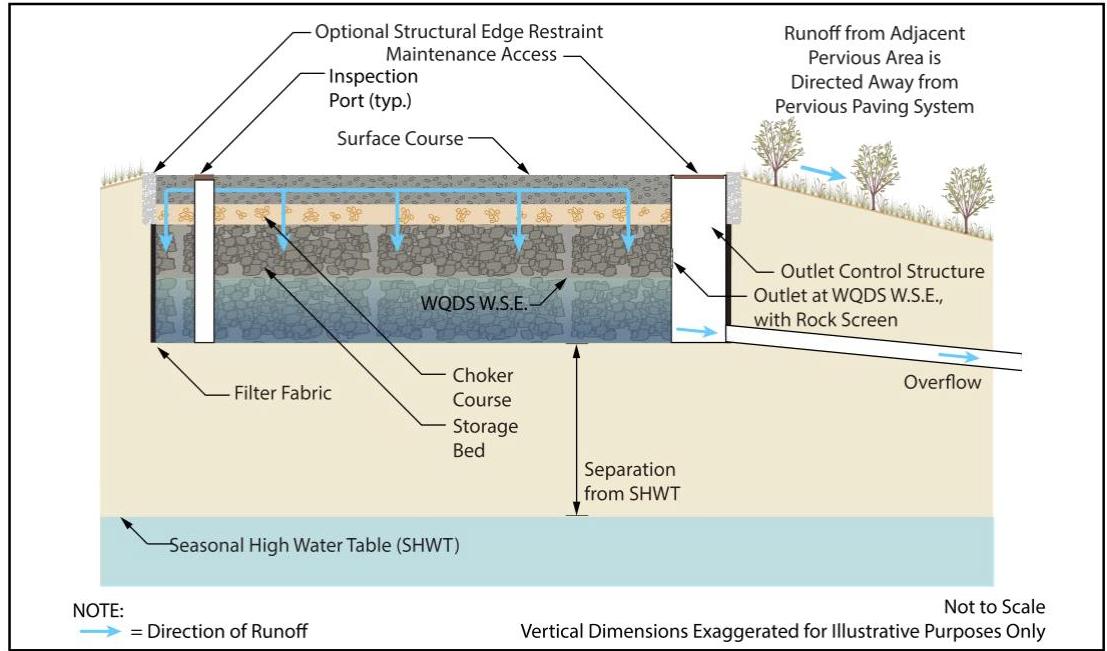
of runoff through the system. The illustrations show possible configurations and flow paths and are not intended to limit the design. The acronym WQDS is the abbreviation for the Water Quality Design Storm.

[OCR image]
Profile View – Porous Pavement Basics

# Surface Course

- The surface course must be designed to support, without lateral movement of the components, the anticipated traffic and other design loads, including additional stresses that may be anticipated at the edges of the installation.
- For a system designed to provide treatment for the WQDS, the minimum tested infiltration rate of the surface course i
PDF page 6, image 1
Mistral ID: img-6.jpeg. Extraction bundle(s): 2023_BMP_9_6_Pervious_Paving_Systems. Original page | Image file
Surrounding OCR excerpt:
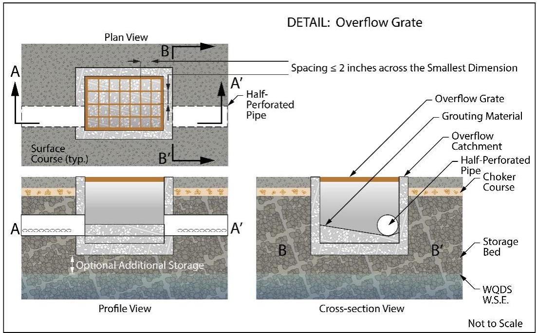
the discharge pipe to facilitate drainage as shown in the detail below. Take note the optional additional storage shown below is for pervious paving systems designed for stormwater runoff quantity control.

[OCR image]
PDF page 7, image 1
Mistral ID: img-7.jpeg. Extraction bundle(s): 2023_BMP_9_6_Pervious_Paving_Systems. Original page | Image file
Surrounding OCR excerpt:
normal operation.

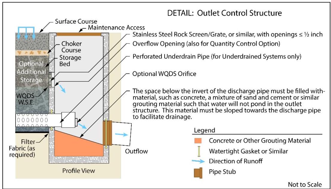
The detail shown below illustrates the requirements for the outlet control structure; the optional elements are solely for illustrative purposes and are not intended to limit the design.

[OCR image]

- Blind connections to downstream facilities are prohibited. Any connection to downstream stormwater management facilities must include access points such as inspections ports and

Page 7
PDF page 10, image 1
Mistral ID: img-8.jpeg. Extraction bundle(s): 2023_BMP_9_6_Pervious_Paving_Systems. Original page | Image file
Surrounding OCR excerpt:
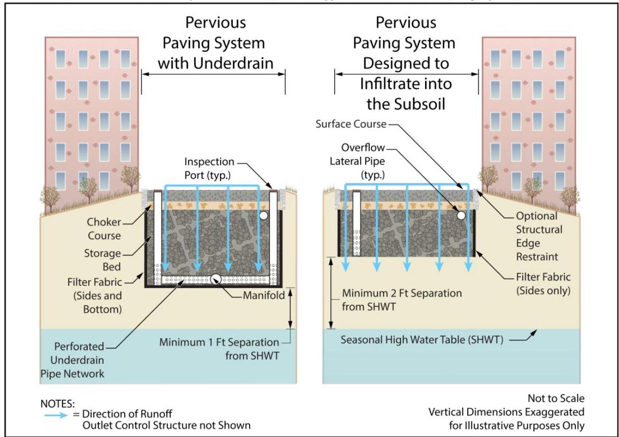
e two types of pervious paving systems. Details for the elements depicted below are included in the respective design criteria.

Cross Section Views – A Comparison of the Two Types of Pervious Paving Systems
[OCR image]
PDF page 12, image 1
Mistral ID: img-9.jpeg. Extraction bundle(s): 2023_BMP_9_6_Pervious_Paving_Systems. Original page | Image file
Surrounding OCR excerpt:
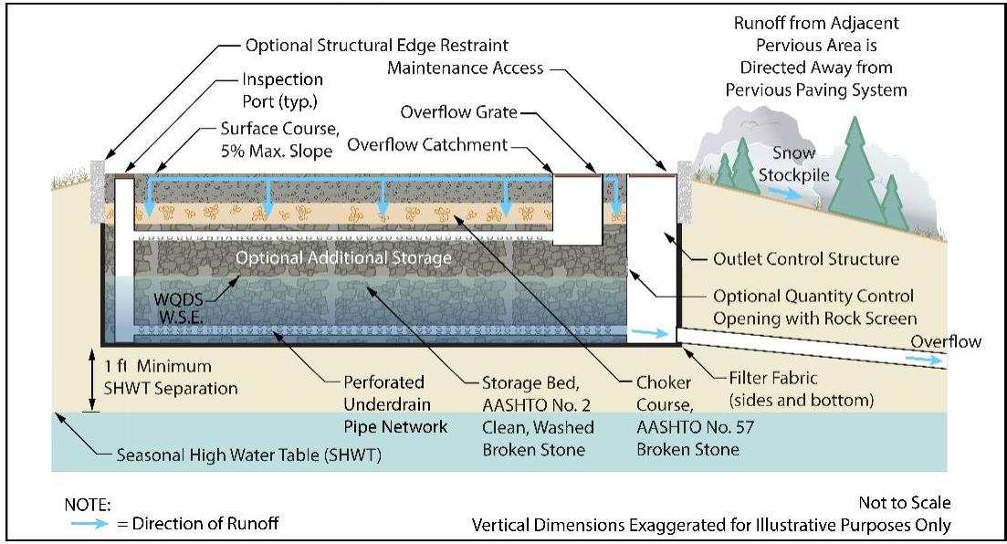
Profile View – Pervious Paving System with Underdrain

[OCR image]
PDF page 15, image 1
Mistral ID: img-10.jpeg. Extraction bundle(s): 2023_BMP_9_6_Pervious_Paving_Systems. Original page | Image file
Surrounding OCR excerpt:
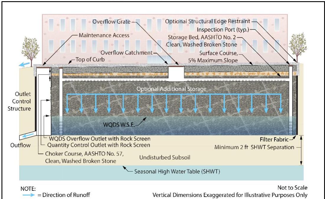
Profile View – Pervious Paving System Designed to Infiltrate into the Subsoil

[OCR image]
PDF page 20, image 1
Mistral ID: img-11.jpeg. Extraction bundle(s): 2023_BMP_9_6_Pervious_Paving_Systems. Original page | Image file
Surrounding OCR excerpt:
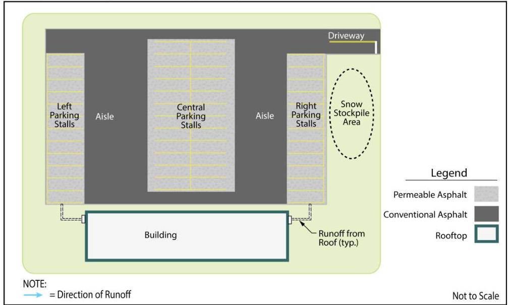
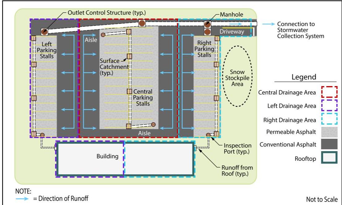
ide detention for larger storm events above invert of the outlet. The sizing calculations for the larger storm events are beyond the scope of this chapter. The layout of the site is illustrated as follows:

[OCR image]

## Step 1: Stormwater Runoff Calculations for the Water Quality Design Storm

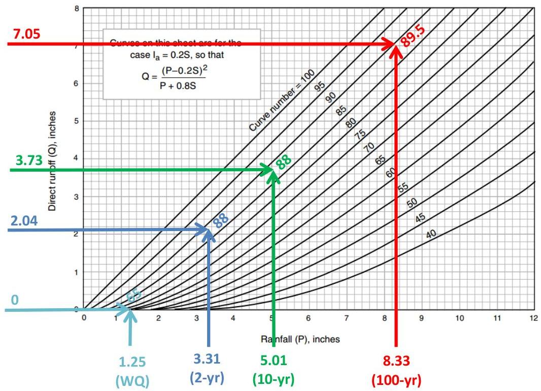
Using the NRCS method described in National Engineering Handbook, Part 630 (NEH) and discussed in Chapter 5: Stormwater Management Quantity and Quality Standards and Computations, the WQDS stormwater runoff volumes were calculated to be as shown on the following page:
PDF page 24, image 1
Mistral ID: img-12.jpeg. Extraction bundle(s): 2023_BMP_9_6_Pervious_Paving_Systems. Original page | Image file
Surrounding OCR excerpt:
ge 7. Additionally, overflow provisions are required for the surface course, as shown in the outlet structure design criteria found on Pages 6 through 8. The site layout is shown in the illustration below:

[OCR image]
PDF page 25, image 1
Mistral ID: img-13.jpeg. Extraction bundle(s): 2023_BMP_9_6_Pervious_Paving_Systems. Original page | Image file
Tables on the same PDF page: Table 9
Surrounding OCR excerpt:
| 4,694 | 0 | 0.00 | 65  |
|  2-year | 3.31 | 13,946 | 4,694 | 9,252 | 2.04 | 88  |
|  10-year | 5.01 | 21,633 | 4,694 | 16,939 | 3.73 | 88  |
|  100-year | 8.33 | 36,666 | 4,694 | 31,972 | 7.05 | 89.5  |

[OCR image]

The Reduced CN can be used to calculate the runoff volume. However, when calculating peak flow rate, a routing calculation must be performed on the pervious paving system.
PDF page 26, image 1
Mistral ID: img-14.jpeg. Extraction bundle(s): 2023_BMP_9_6_Pervious_Paving_Systems. Original page | Image file
Tables on the same PDF page: Table 10
Surrounding OCR excerpt:
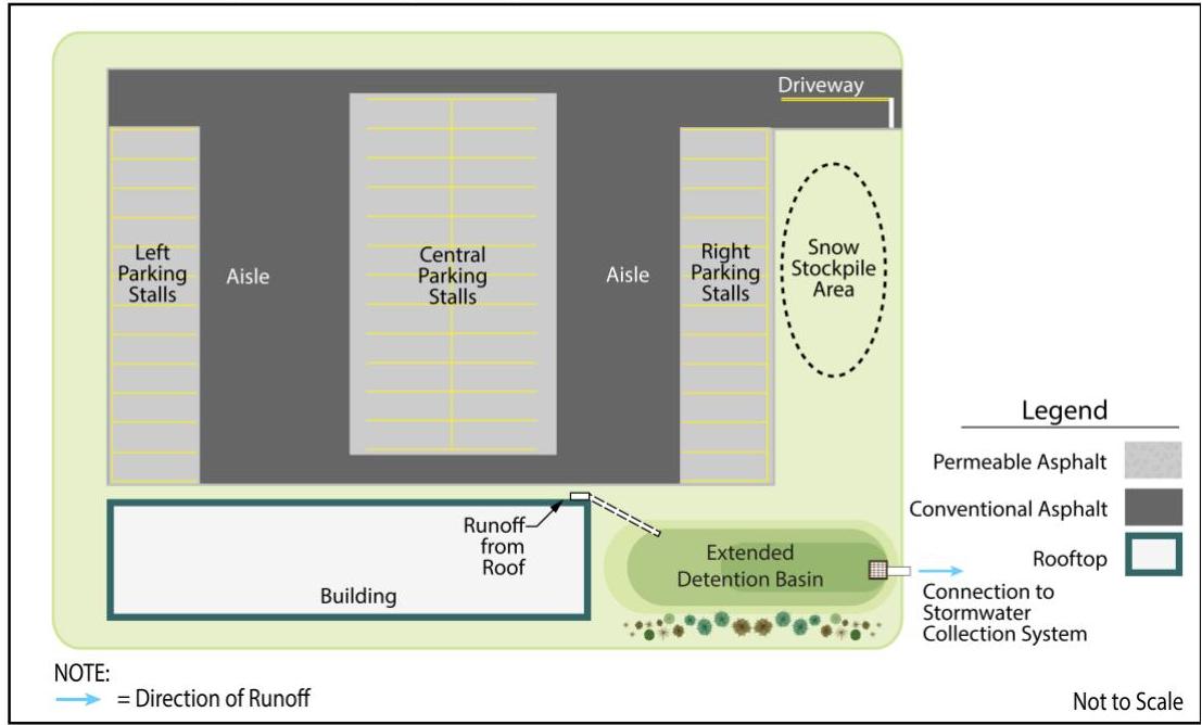
Unlike Example 1, the clean roof runoff is not directed to the storage bed because a pervious paving system with an underdrain cannot be used to reduce volume. The layout of the site is illustrated below:

[OCR image]
PDF page 27, image 1
Mistral ID: img-15.jpeg. Extraction bundle(s): 2023_BMP_9_6_Pervious_Paving_Systems. Original page | Image file
Tables on the same PDF page: Table 11
Surrounding OCR excerpt:
lls (0.125 acres) | Driveway and Aisles (0.125 acres) | 1  |

The area of additional inflow from conventional pavement is not greater than three times the area occupied by the pervious asphalt paving area.

[OCR image]
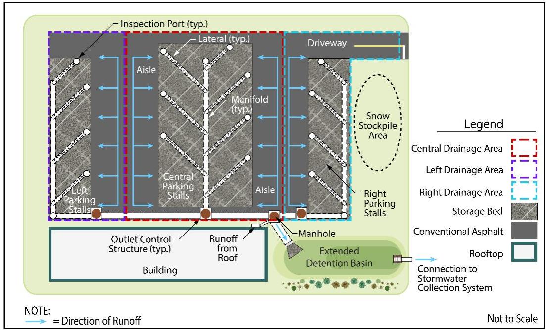
Example 2 – Proposed Site Drainage Layout

## Step 1: Runoff Calculations for the Water Quality Design Storm

Using the NRCS method described in National Engineering Handbook, Part 630 (NEH) and discussed in Chapter 5, the WQDS runoff volumes were calculated to be as shown in the table at the top of the following page: