Extracted images: Small-Scale Bioretention Systems
Printed revision: March 2021.
Back to source | Original PDF | Image metadata
Original Mistral crops are preserved byte for byte. A crop can be a figure, table, equation, or other visual; no visual content is inferred as a numerical rule. Record and table associations use the same PDF page unless a direct image placeholder is identified. Nearby OCR excerpts are context, not verified captions.
PDF page 1, image 1
Mistral ID: img-0.jpeg. Extraction bundle(s): 2023_BMP_9_7_Small_Scale_Bioretention_Systems. Original page | Image file
Tables on the same PDF page: Table 1
Surrounding OCR excerpt:
# 9.7 SMALL-SCALE BIORETENTION SYSTEMS

[OCR image]

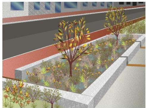
Small-scale bioretention systems are stormwater management facilities used to address the stormwater quality and quantity impacts of land development. The system consists of a soil bed planted with vegetation; it can be underdrained, or runoff can infiltrate into the subsoil. Pollutants are treated through the processes of settling, plus uptake and filtration by the vegetation. Pollutants are also trea
PDF page 3, image 1
Mistral ID: img-1.jpeg. Extraction bundle(s): 2023_BMP_9_7_Small_Scale_Bioretention_Systems. Original page | Image file
Surrounding OCR excerpt:
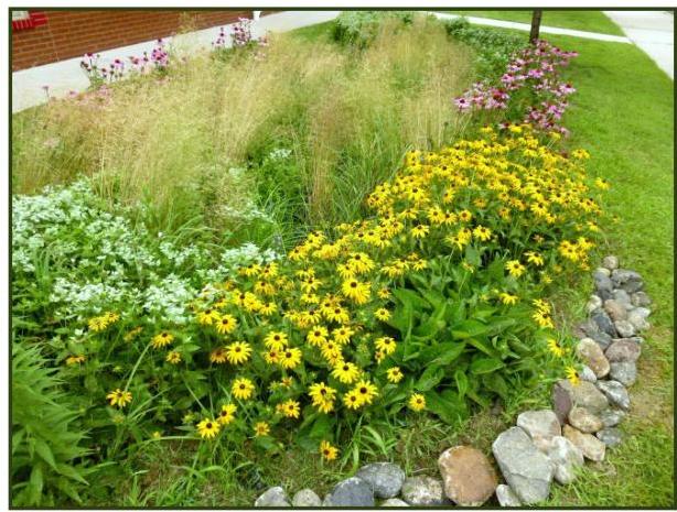
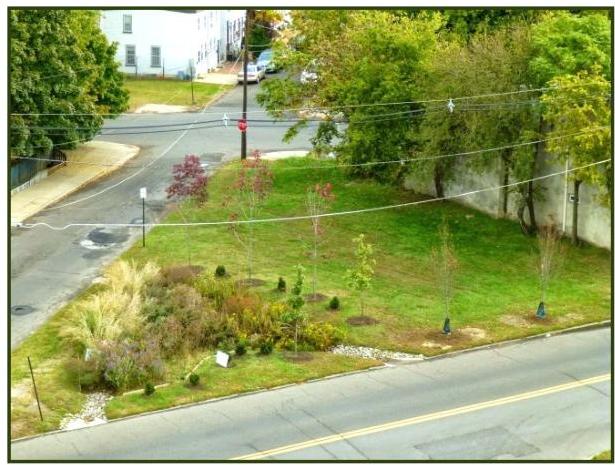
tings, small-scale bioretention systems may look like small gardens situated on a portion of a lot, such as the small-scale bioretention systems, called rain gardens, shown in the following two photographs:

[OCR image]

[OCR image]

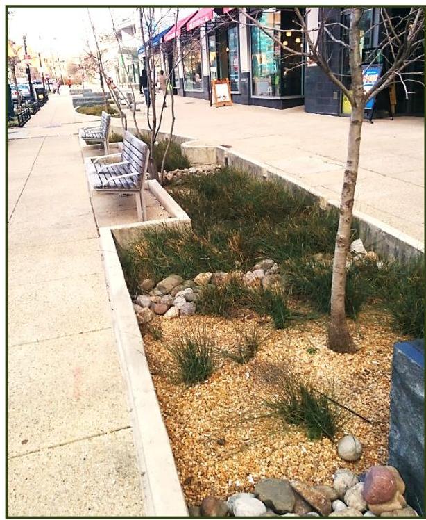
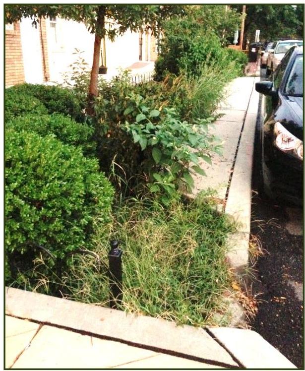
Alternatively, such systems may be constructed within a sidewalk or along a roadway, like those depicted in the following two photographs, which may be referred to as stormwater planters or rain gardens:

[OCR image]

[OCR image]
PDF page 3, image 2
Mistral ID: img-2.jpeg. Extraction bundle(s): 2023_BMP_9_7_Small_Scale_Bioretention_Systems. Original page | Image file
Surrounding OCR excerpt:
tion systems may look like small gardens situated on a portion of a lot, such as the small-scale bioretention systems, called rain gardens, shown in the following two photographs:

[OCR image]

[OCR image]

Alternatively, such systems may be constructed within a sidewalk or along a roadway, like those depicted in the following two photographs, which may be referred to as stormwater planters or rain gardens:

[OCR image]

[OCR image]
PDF page 3, image 3
Mistral ID: img-3.jpeg. Extraction bundle(s): 2023_BMP_9_7_Small_Scale_Bioretention_Systems. Original page | Image file
Surrounding OCR excerpt:
)

Alternatively, such systems may be constructed within a sidewalk or along a roadway, like those depicted in the following two photographs, which may be referred to as stormwater planters or rain gardens:

[OCR image]

[OCR image]
PDF page 3, image 4
Mistral ID: img-4.jpeg. Extraction bundle(s): 2023_BMP_9_7_Small_Scale_Bioretention_Systems. Original page | Image file
Surrounding OCR excerpt:
ems may be constructed within a sidewalk or along a roadway, like those depicted in the following two photographs, which may be referred to as stormwater planters or rain gardens:

[OCR image]

[OCR image]
PDF page 4, image 1
Mistral ID: img-5.jpeg. Extraction bundle(s): 2023_BMP_9_7_Small_Scale_Bioretention_Systems. Original page | Image file
Surrounding OCR excerpt:
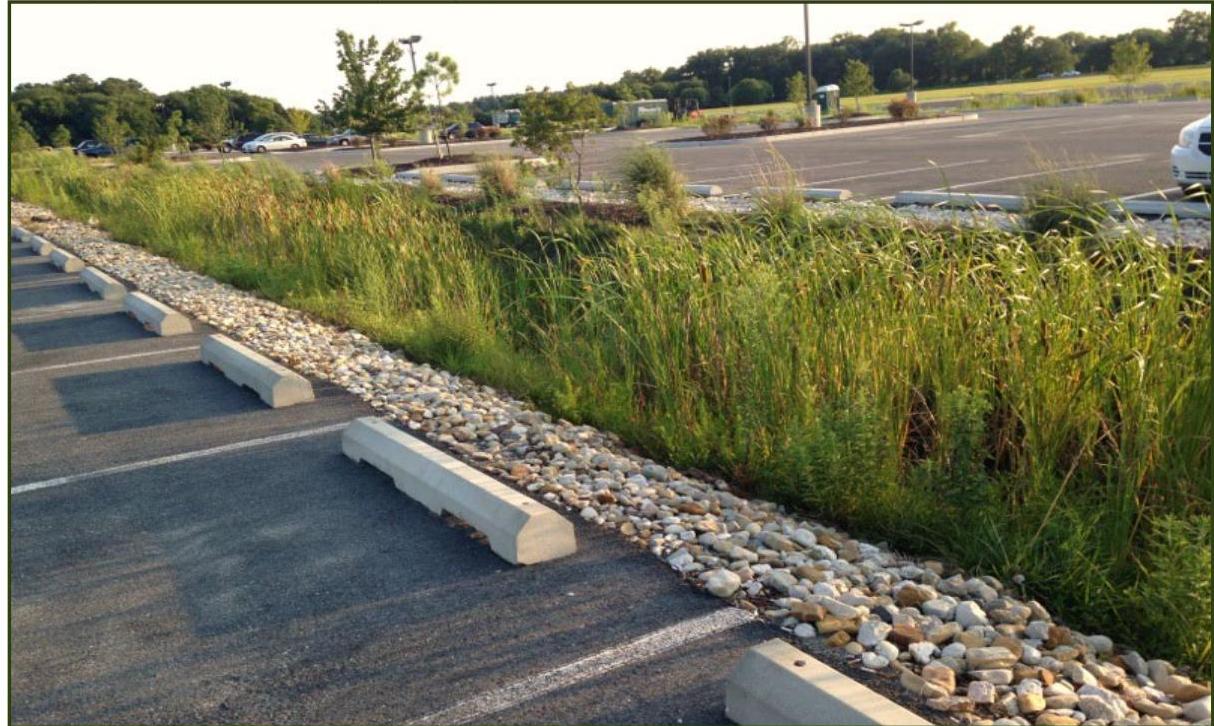
Small-scale bioretention systems may also be used as a conveyance system such as the bioswale in the parking median shown in the photograph below.

[OCR image]

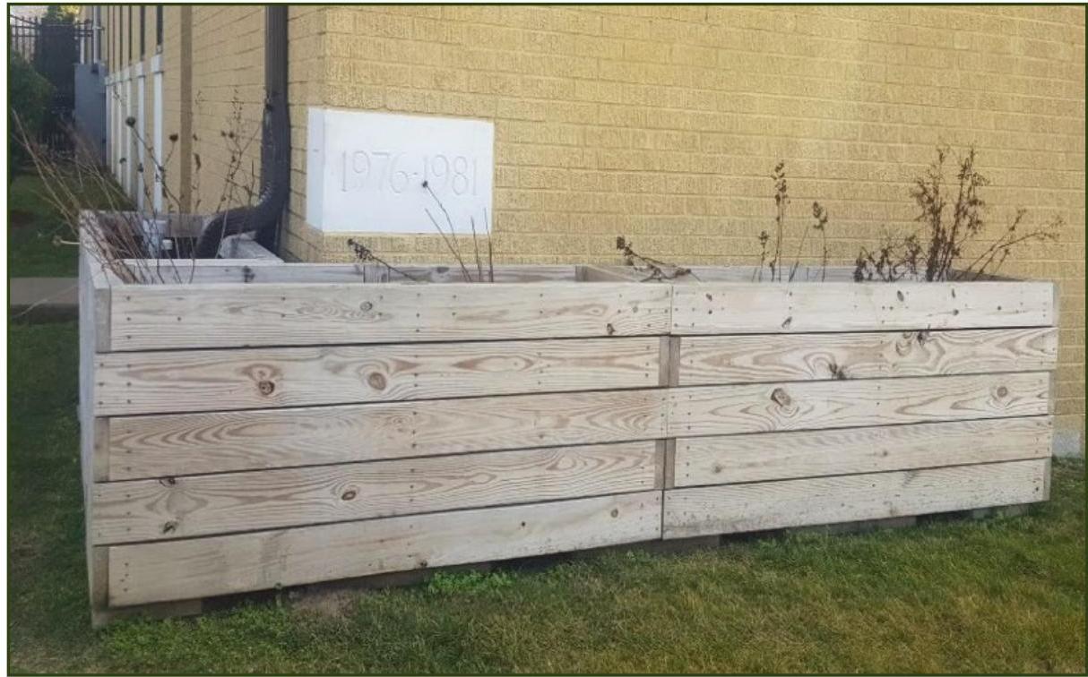
Small-scale bioretention systems may even be contained within a wooden or concrete box, generally called planter boxes or downspout planter boxes, as shown in the following photograph:

[OCR image]
PDF page 4, image 2
Mistral ID: img-6.jpeg. Extraction bundle(s): 2023_BMP_9_7_Small_Scale_Bioretention_Systems. Original page | Image file
Surrounding OCR excerpt:
-5.jpeg](img-5.jpeg)

Small-scale bioretention systems may even be contained within a wooden or concrete box, generally called planter boxes or downspout planter boxes, as shown in the following photograph:

[OCR image]
PDF page 5, image 1
Mistral ID: img-7.jpeg. Extraction bundle(s): 2023_BMP_9_7_Small_Scale_Bioretention_Systems. Original page | Image file

Tables on the same PDF page: Table 2
Surrounding OCR excerpt:
# Applications

[OCR image]

Pursuant to N.J.A.C. 7:8-5.2(a)(2), the minimum design and performance standards for groundwater recharge, stormwater runoff quality and stormwater runoff quantity at N.J.A.C. 7:8-5.4, 5.5 and 5.6 shall be met by incorporating green infrastructure in accordance with N.J.A.C. 7:8-5.3.

[OCR image]

Small-scale bioretention systems may be designed to convey storm events larger than the Wate
PDF page 5, image 2
Mistral ID: img-8.jpeg. Extraction bundle(s): 2023_BMP_9_7_Small_Scale_Bioretention_Systems. Original page | Image file

Tables on the same PDF page: Table 2
Surrounding OCR excerpt:
ds for groundwater recharge, stormwater runoff quality and stormwater runoff quantity at N.J.A.C. 7:8-5.4, 5.5 and 5.6 shall be met by incorporating green infrastructure in accordance with N.J.A.C. 7:8-5.3.

[OCR image]

Small-scale bioretention systems may be designed to convey storm events larger than the Water Quality Design Storm (WQDS); however, regardless of the design storm chosen, all small-scale bioretention systems must be designed for stability and in accordance with the Standards for Soil Erosion and Sediment Control in New Jersey.

[OCR image]

Only small-scale bioretention systems designed t
PDF page 5, image 3
Mistral ID: img-9.jpeg. Extraction bundle(s): 2023_BMP_9_7_Small_Scale_Bioretention_Systems. Original page | Image file

Tables on the same PDF page: Table 2
Surrounding OCR excerpt:
however, regardless of the design storm chosen, all small-scale bioretention systems must be designed for stability and in accordance with the Standards for Soil Erosion and Sediment Control in New Jersey.

[OCR image]

Only small-scale bioretention systems designed to infiltrate into the subsoil may be used to meet the groundwater recharge requirements. If designed with an underdrain, a small-scale bioretention system cannot be used to meet these requirements. For more information on computing groundwater recharge, see Chapter 6: Groundwater Recharge.

[OCR image]

The depth of the soil bed and the ty
PDF page 5, image 4
Mistral ID: img-10.jpeg. Extraction bundle(s): 2023_BMP_9_7_Small_Scale_Bioretention_Systems. Original page | Image file

Tables on the same PDF page: Table 2
Surrounding OCR excerpt:
ts. If designed with an underdrain, a small-scale bioretention system cannot be used to meet these requirements. For more information on computing groundwater recharge, see Chapter 6: Groundwater Recharge.

[OCR image]

The depth of the soil bed and the type of vegetation determine the TSS removal rate, as shown in the table below. To merit the approved TSS removal rate of 80%, small-scale bioretention systems must be designed to treat the Water Quality Design Storm and in accordance with all of the following criteria.

|  Desired TSS Removal Rate | Design Parameters  |   |
| --- | --- | --- |
|   |  Minimum Depth of
PDF page 6, image 1
Mistral ID: img-11.jpeg. Extraction bundle(s): 2023_BMP_9_7_Small_Scale_Bioretention_Systems. Original page | Image file
Surrounding OCR excerpt:
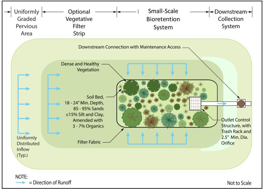
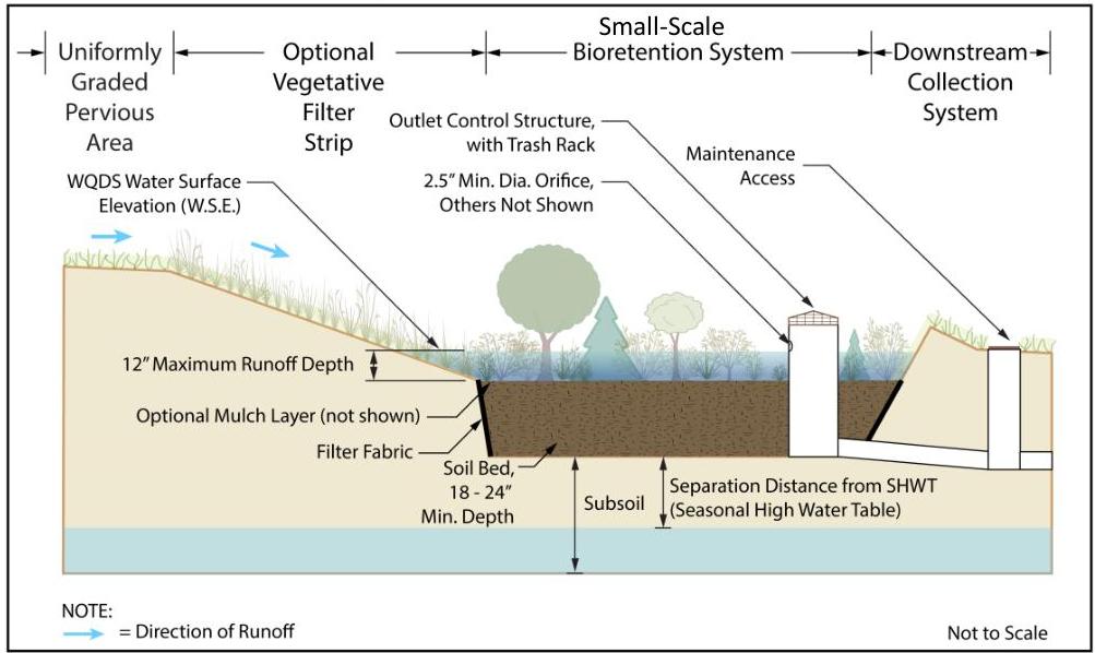
common surface elements, which are shown below. In the following illustrations, a vegetative filter strip provides pretreatment and a downstream collection system receives runoff that does not infiltrate.

[OCR image]

[OCR image]
PDF page 6, image 2
Mistral ID: img-12.jpeg. Extraction bundle(s): 2023_BMP_9_7_Small_Scale_Bioretention_Systems. Original page | Image file
Surrounding OCR excerpt:
ch are shown below. In the following illustrations, a vegetative filter strip provides pretreatment and a downstream collection system receives runoff that does not infiltrate.

[OCR image]

[OCR image]
PDF page 9, image 1
Mistral ID: img-13.jpeg. Extraction bundle(s): 2023_BMP_9_7_Small_Scale_Bioretention_Systems. Original page | Image file
Surrounding OCR excerpt:
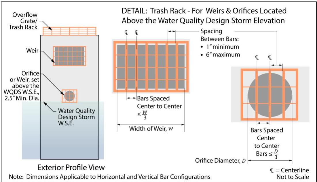
y affect the hydraulic performance of the outlet pipe or structure;
☐ Constructed of rigid, durable and corrosion-resistant material; and
☐ Designed to withstand a perpendicular live loading of 300 lbs/sf.

[OCR image]

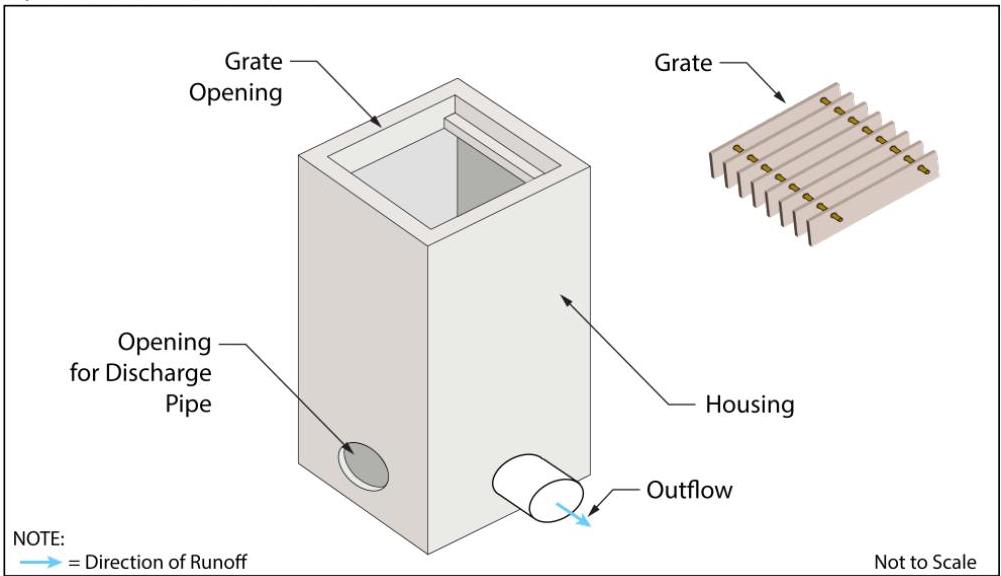
- An overflow grate is designed to prevent obstruction of the overflow structure. If an outlet structure has an overflow grate, the grate must comply with the following requirements:

Page 9
PDF page 10, image 1
Mistral ID: img-14.jpeg. Extraction bundle(s): 2023_BMP_9_7_Small_Scale_Bioretention_Systems. Original page | Image file
Surrounding OCR excerpt:
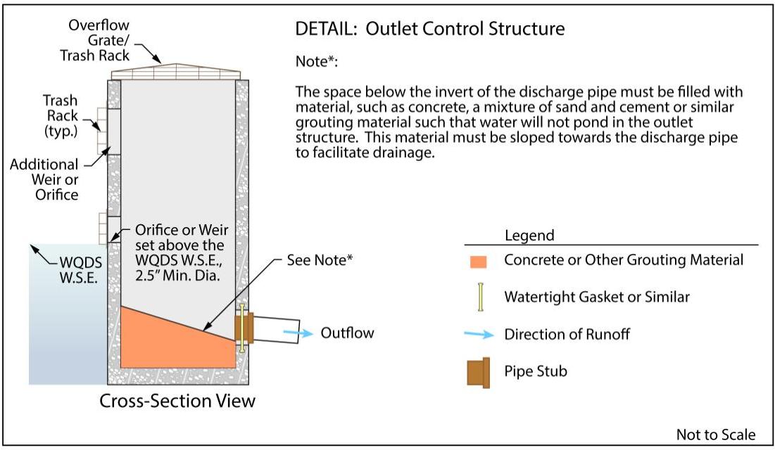
d and cement, or similar grouting material, such that water will not pond in the outlet structure. This material must be sloped towards the discharge pipe to facilitate drainage, as shown on the next page.

[OCR image]

- The minimum diameter of any overflow orifice is 2.5 inches.
- Blind connections to downstream facilities are prohibited. Any connection to down-gradient stormwater management facilities must include access points such as inspections ports and manholes, for visual inspection and maintenance, as appropriate, to prevent blockage of flow and ensure operation as intended. All entrance points must adhere
PDF page 11, image 1
Mistral ID: img-15.jpeg. Extraction bundle(s): 2023_BMP_9_7_Small_Scale_Bioretention_Systems. Original page | Image file
Surrounding OCR excerpt:
# Square Yard Drain Detail

[OCR image]

- In instances where the lowest invert in the outlet or overflow structure is below the flood hazard area design flood or tide elevation in a downstream waterway or stormwater collection system, the effects of tailwater on the hydraulic design of the underdrain and overflow systems, as well as any stormwater quantity control outlets, must be analyzed. Two methods to analyze tailwater are:

☐ A simple
PDF page 15, image 1
Mistral ID: img-16.jpeg. Extraction bundle(s): 2023_BMP_9_7_Small_Scale_Bioretention_Systems. Original page | Image file
Surrounding OCR excerpt:
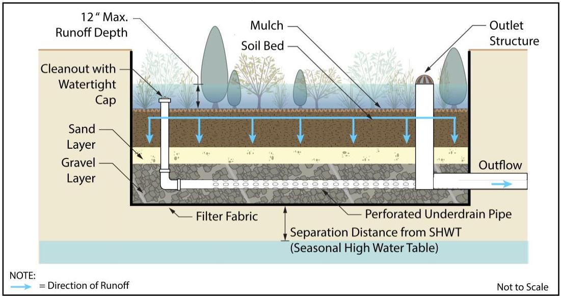
# Flat Bottom Small-Scale Bioretention System with Underdrain - Profile View

[OCR image]

## Volume Reduction in Small-Scale Bioretention Systems with an Underdrain

The soil bed in a small-scale bioretention system with an underdrain will absorb and retain a portion of the runoff that is directed into it, thus reducing the volume of runoff that will reach downstream facilities. The maximum amount of water that the soil bed is capable of retaining is called the field capacity. However, in
PDF page 19, image 1
Mistral ID: img-17.jpeg. Extraction bundle(s): 2023_BMP_9_7_Small_Scale_Bioretention_Systems. Original page | Image file
Surrounding OCR excerpt:
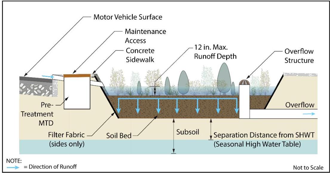
small-scale bioretention system designed as a rain garden to infiltrate into the subsoil. Note that an MTD is used for pretreatment so that exfiltration may be used in the stormwater routing calculations.

[OCR image]

Small-Scale Bioretention System with Infiltration - Profile View

Page 19
PDF page 20, image 1
Mistral ID: img-18.jpeg. Extraction bundle(s): 2023_BMP_9_7_Small_Scale_Bioretention_Systems. Original page | Image file
Surrounding OCR excerpt:
es of Small-Scale Bioretention Systems

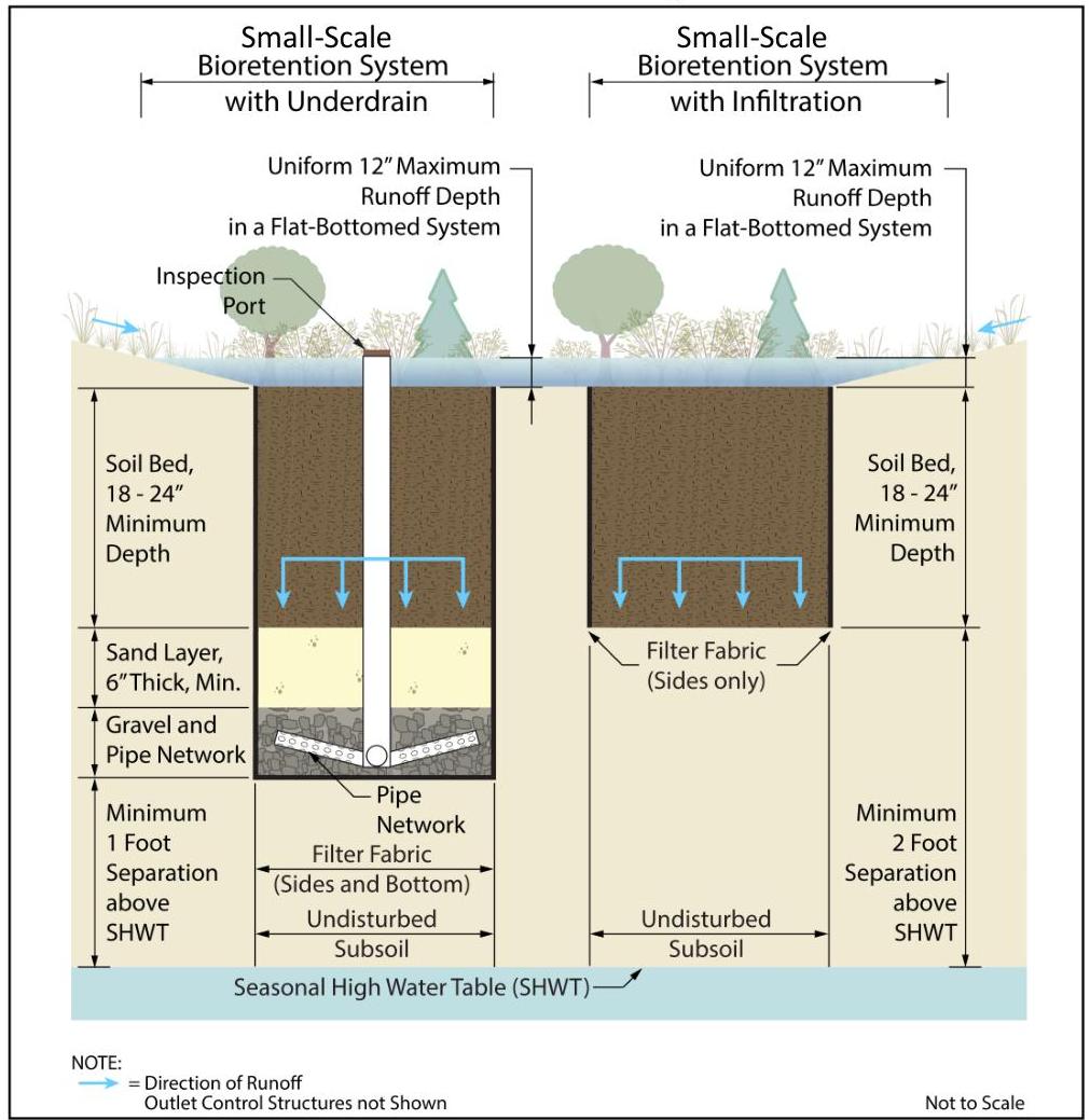
The following illustration shows the differences between the basic components of a small-scale bioretention system with an underdrain and one designed to infiltrate.

[OCR image]
PDF page 22, image 1
Mistral ID: img-19.jpeg. Extraction bundle(s): 2023_BMP_9_7_Small_Scale_Bioretention_Systems. Original page | Image file
Surrounding OCR excerpt:
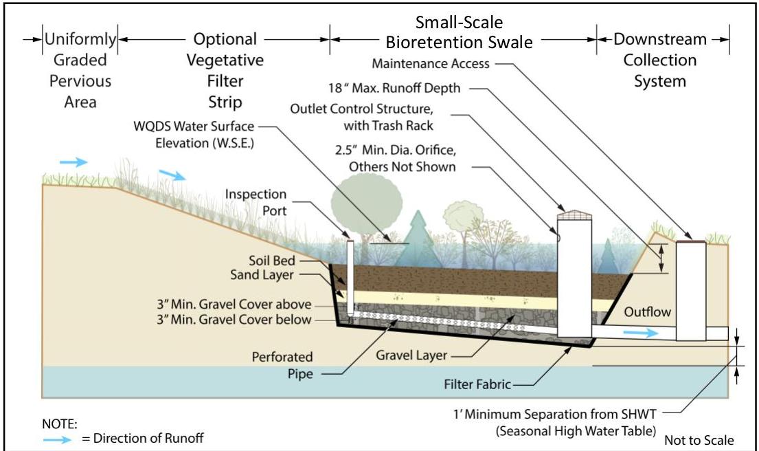
r above and below. The outlet control structure also serves as the down-gradient inspection port. Additional maintenance access is provided at the connection to the downstream stormwater collection system.

[OCR image]
Sloped-Bottom Small-Scale Bioretention Swale with Underdrain - Profile View

## Stormwater Tree Pit

- A stormwater tree pit is more than a tree pit that is normally constructed on sidewalk for landscaping purposes. A stormwater tree pit must have a soil bed, as described on Page 5. Since the soil bed must support the growth of the tree, the minimum depth of 18 inches may not be sufficient. A gravel-fi
PDF page 26, image 1
Mistral ID: img-20.jpeg. Extraction bundle(s): 2023_BMP_9_7_Small_Scale_Bioretention_Systems. Original page | Image file
Tables on the same PDF page: Table 6 | Table 7
Surrounding OCR excerpt:
etermine the volume of runoff leaving the site. This means that 609.15 cf of runoff would leave the site in this example.

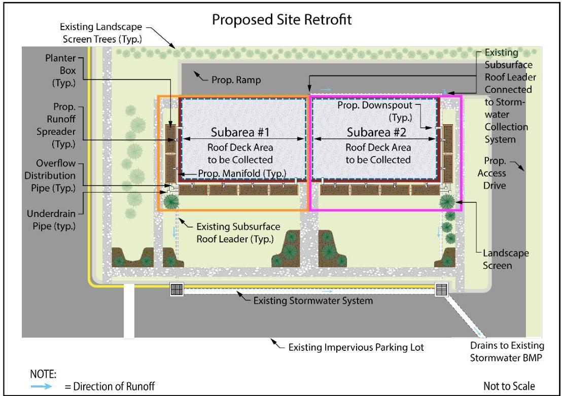
Illustrations of the planter box system are found below and on the following page.

[OCR image]
Example 1 - Plan View
PDF page 27, image 1
Mistral ID: img-21.jpeg. Extraction bundle(s): 2023_BMP_9_7_Small_Scale_Bioretention_Systems. Original page | Image file
Surrounding OCR excerpt:
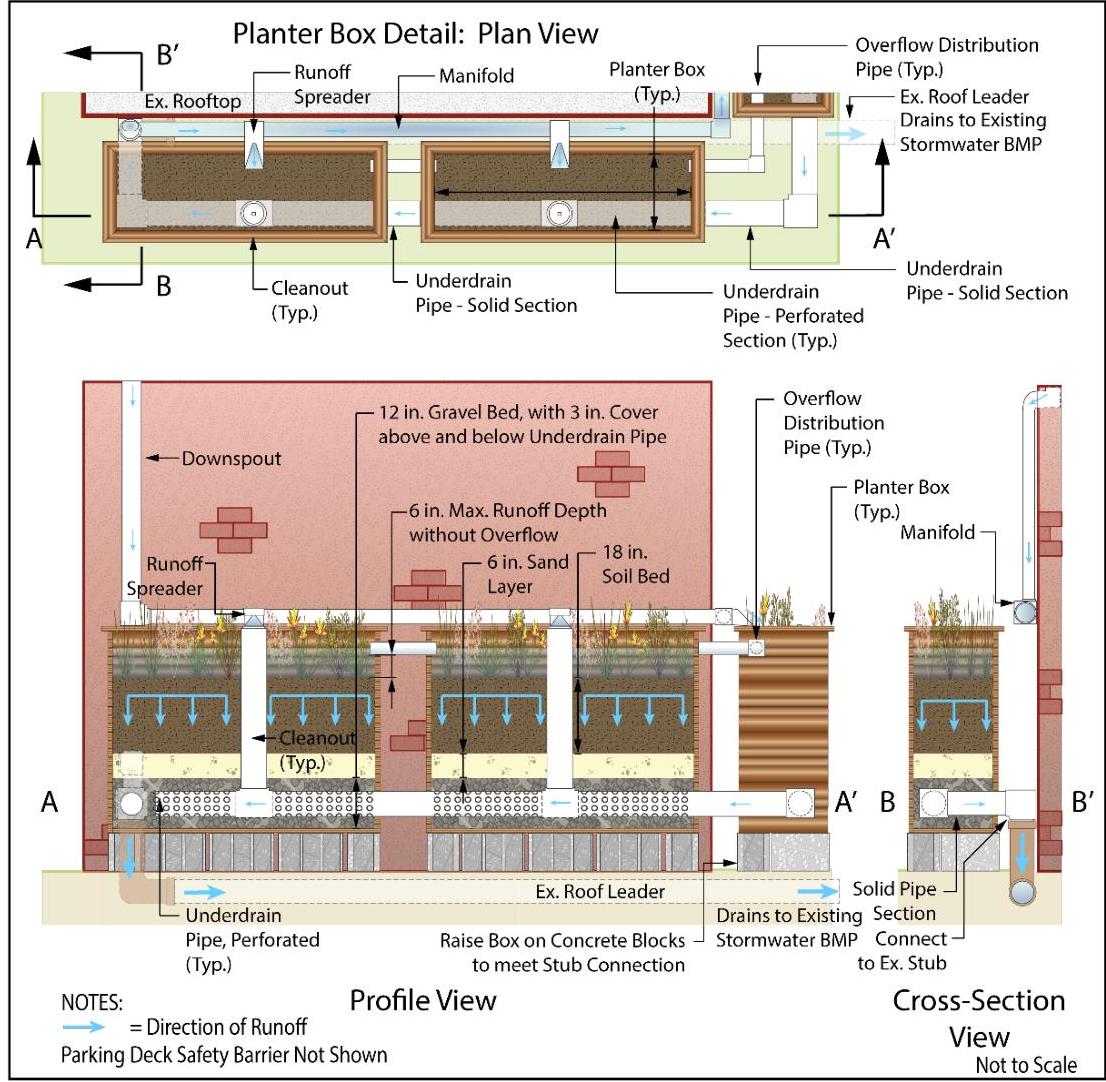
Example 1 – Detail Views

[OCR image]
PDF page 28, image 1
Mistral ID: img-22.jpeg. Extraction bundle(s): 2023_BMP_9_7_Small_Scale_Bioretention_Systems. Original page | Image file
Surrounding OCR excerpt:
umber (CN) of 98 for asphalt.

# Step 2: Sizing of the Rain Garden

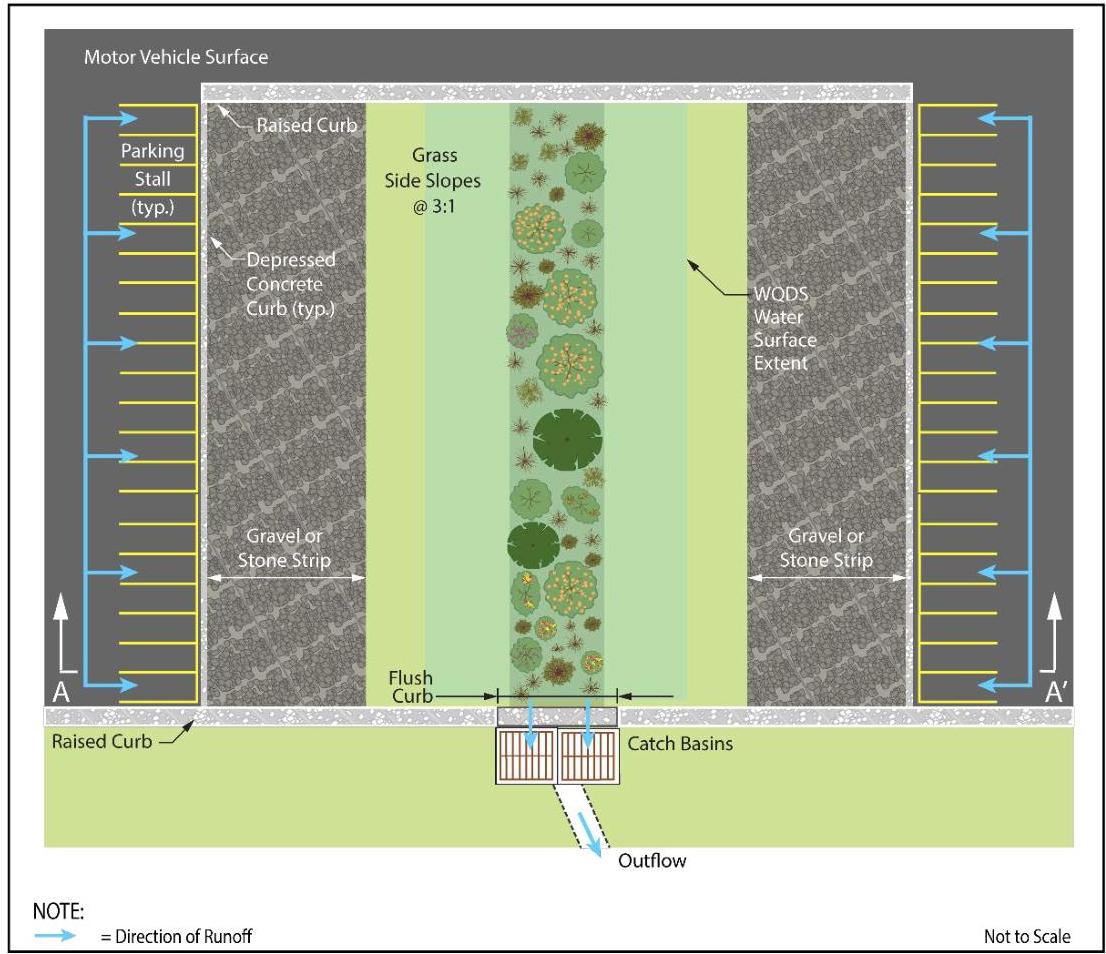
The rain garden is in the center of the parking area, separating two rows of parking spaces. A plan view of the design is provided below:

[OCR image]

Example 2 - Plan View
PDF page 29, image 1
Mistral ID: img-23.jpeg. Extraction bundle(s): 2023_BMP_9_7_Small_Scale_Bioretention_Systems. Original page | Image file
Surrounding OCR excerpt:
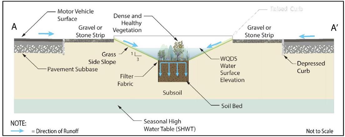
A section view at the lower limit of the rain garden is shown below. For simplicity, fencing or another barrier to prevent vehicular intrusion into the system are omitted.

[OCR image]
Example 2 - Section View

The rain garden is designed with grassed side slopes of 3:1 (horizontal distance to vertical distance) on the sides adjacent to the parking stalls. The footprint of the soil bed is 465 sf or 3 ft wide by 155 ft long. The width of the rain garden becomes 9 feet and 12 feet at the elevations of 1 foot and 1.5 feet above the soil bed.

The tested soil permeability rate of the sub
PDF page 31, image 1
Mistral ID: img-24.jpeg. Extraction bundle(s): 2023_BMP_9_7_Small_Scale_Bioretention_Systems. Original page | Image file
Tables on the same PDF page: Table 10
Surrounding OCR excerpt:
l to vertical)  |
|  Tested Permeability of Soil Bed = | 8 in/hr  |
|  Tested Permeability of Subsoil = | 2 in/hr  |
|  Depth to the Seasonal High Water Table (SHWT) = | 8 ft below existing ground level  |

[OCR image]
PDF page 35, image 1
Mistral ID: img-25.jpeg. Extraction bundle(s): 2023_BMP_9_7_Small_Scale_Bioretention_Systems. Original page | Image file
Surrounding OCR excerpt:
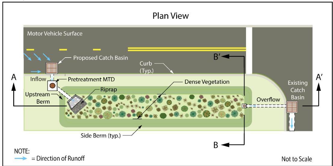
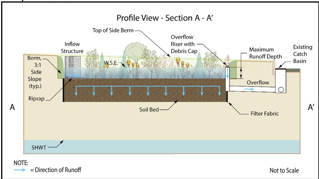
sectional views. Take note that the horizontal distance between the inflow and outflow riser allows for maximum contact time between the runoff and the vegetation, which promotes greater pollutant removal.

[OCR image]
Example 3 – Plan View

[OCR image]
Example 3 – Profile View
PDF page 35, image 2
Mistral ID: img-26.jpeg. Extraction bundle(s): 2023_BMP_9_7_Small_Scale_Bioretention_Systems. Original page | Image file
Surrounding OCR excerpt:
ance between the inflow and outflow riser allows for maximum contact time between the runoff and the vegetation, which promotes greater pollutant removal.

[OCR image]
Example 3 – Plan View

[OCR image]
Example 3 – Profile View
PDF page 36, image 1
Mistral ID: img-27.jpeg. Extraction bundle(s): 2023_BMP_9_7_Small_Scale_Bioretention_Systems. Original page | Image file
Surrounding OCR excerpt:
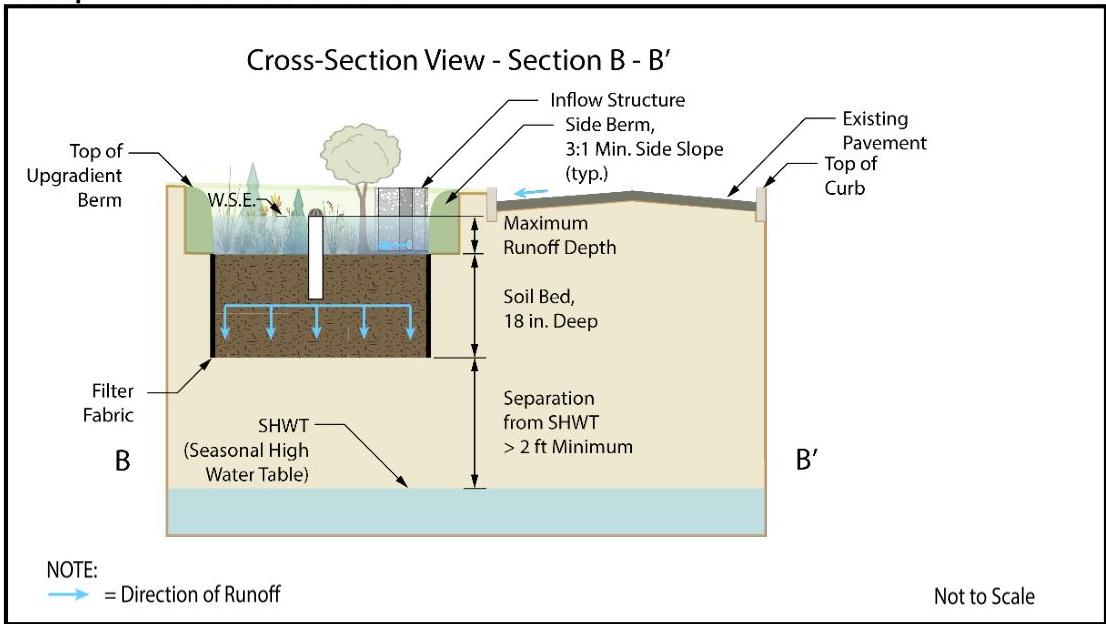
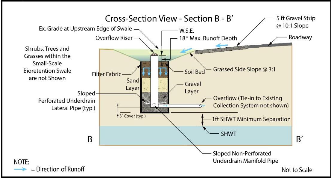
Example 3 – Cross-Section View

[OCR image]

NOTE:
Cross-Section View - Section B - B'
= Direction of Runoff
Not to Scale

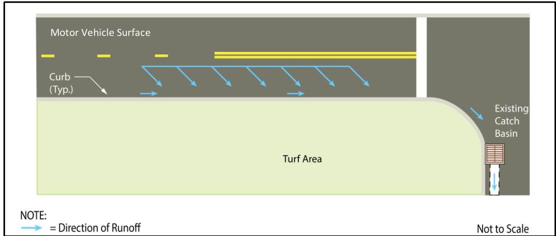
Example 4: For the existing uncurbed section of motor vehicle surface illustrated below, design a small-scale bioretention swale with an underdrain to treat the runoff generated by the WQDS. Runoff will enter the proposed system as overland flow from the adjacent road surface. Additionally, a connection to the existing downs
PDF page 36, image 2
Mistral ID: img-28.jpeg. Extraction bundle(s): 2023_BMP_9_7_Small_Scale_Bioretention_Systems. Original page | Image file
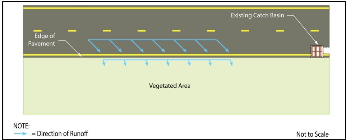
Surrounding OCR excerpt:
a = 5,000 sf of paved road surface
Pavement NRCS Curve Number (CN) = 98
Soil Bed Depth = 18 in
Assumed Design Permeability of Soil Bed = 4 in/hr
WQDS Depth = 18 in = 1.5 ft

Example 4 – Existing Conditions

[OCR image]
PDF page 37, image 1
Mistral ID: img-29.jpeg. Extraction bundle(s): 2023_BMP_9_7_Small_Scale_Bioretention_Systems. Original page | Image file
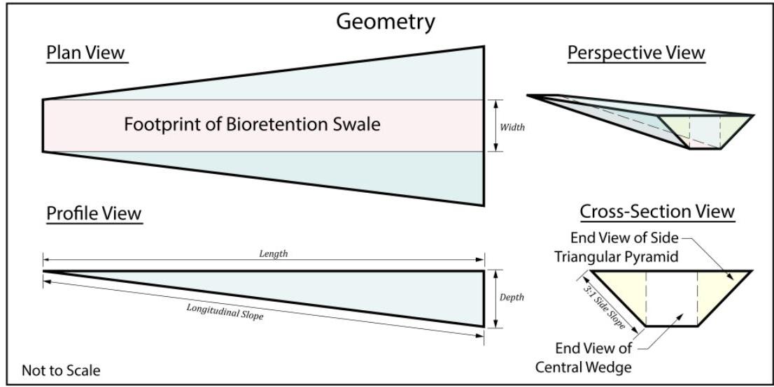
Surrounding OCR excerpt:
edge flanked by two symmetrical triangular pyramids, shown in the following illustration. The ends of the two pyramids are shaded in yellow and that of the central wedge in white in the cross-section view.

[OCR image]

Example 4 – Geometry

Runoff will occupy not only the footprint of the swale, shown in pink in the plan view portion of the above illustration, but also the two side pyramids shown in blue. Failure to account for this additional volume results in both an oversized swale and the infiltration, during larger storm events, of more
PDF page 39, image 1
Mistral ID: img-30.jpeg. Extraction bundle(s): 2023_BMP_9_7_Small_Scale_Bioretention_Systems. Original page | Image file
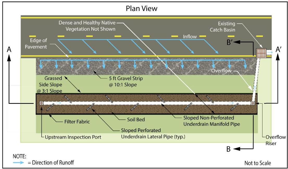
Surrounding OCR excerpt:
ess runoff to the down-gradient collection system. The overall size of the swale in this example includes end berms as transition areas to the existing grade elevation to account for this additional depth.

[OCR image]
PDF page 40, image 1
Mistral ID: img-31.jpeg. Extraction bundle(s): 2023_BMP_9_7_Small_Scale_Bioretention_Systems. Original page | Image file
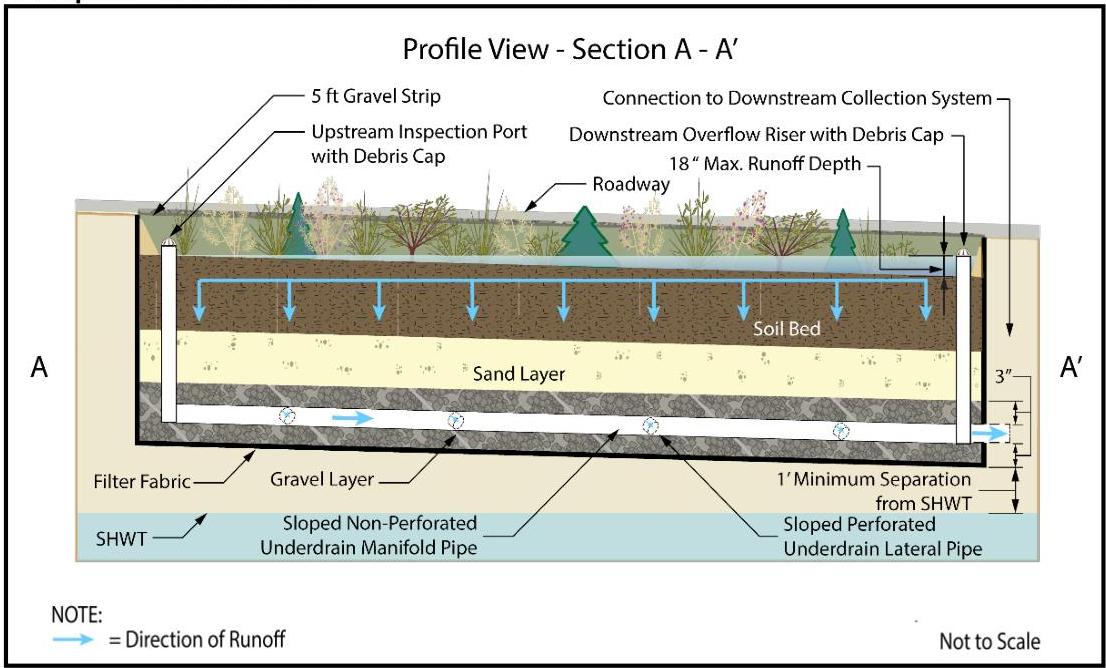
Surrounding OCR excerpt:
Example 4 – Profile View

[OCR image]

Example 4 – Cross-Section View

[OCR image]
PDF page 40, image 2
Mistral ID: img-32.jpeg. Extraction bundle(s): 2023_BMP_9_7_Small_Scale_Bioretention_Systems. Original page | Image file
Surrounding OCR excerpt:
Example 4 – Profile View

[OCR image]

Example 4 – Cross-Section View

[OCR image]
PDF page 43, image 1
Mistral ID: img-33.jpeg. Extraction bundle(s): 2023_BMP_9_7_Small_Scale_Bioretention_Systems. Original page | Image file
Surrounding OCR excerpt:
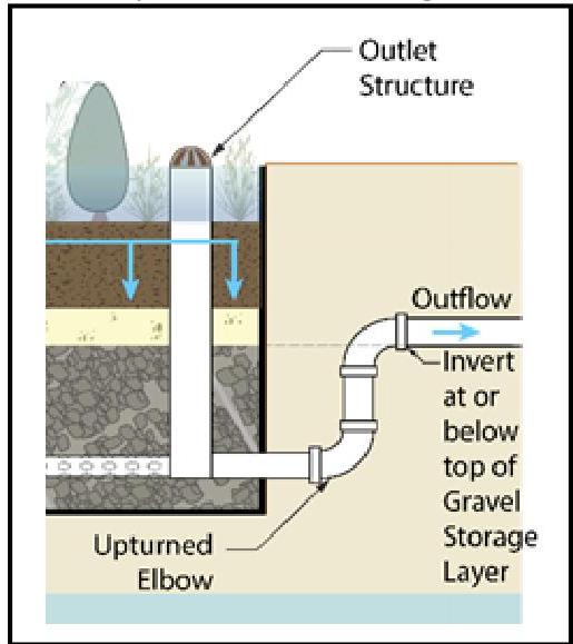
signer may wish to include the upturned elbow configuration shown in the illustration below to slow the discharge and increase the potential for increased biological processes to occur in the gravel layer.

[OCR image]
Detail: Upturned Elbow Configuration

## Soil Characteristics

For small-scale bioretention systems designed to infiltrate into the subsoil, soils are perhaps the most important consideration for site suitability. In general, County Soil Surveys may be used to obtain necessary soil data for planning and preliminary design of bioretention systems. However, as previously mentioned, for final design and c