Extracted images: Small-Scale Infiltration Basins
Printed revision: March 2021.
Back to source | Original PDF | Image metadata
Original Mistral crops are preserved byte for byte. A crop can be a figure, table, equation, or other visual; no visual content is inferred as a numerical rule. Record and table associations use the same PDF page unless a direct image placeholder is identified. Nearby OCR excerpts are context, not verified captions.
PDF page 1, image 1
Mistral ID: img-0.jpeg. Extraction bundle(s): 2023_BMP_9_8_Small_Scale_Infiltration_Basins. Original page | Image file
Tables on the same PDF page: Table 1
Surrounding OCR excerpt:
# 9.8 SMALL-SCALE INFILTRATION BASINS

[OCR image]

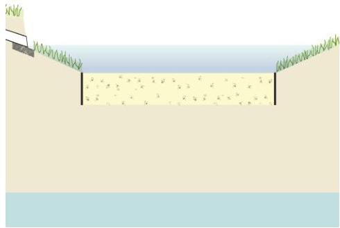
Small-scale infiltration basins are stormwater management systems constructed with highly permeable components designed to both maximize the removal of pollutants from stormwater and to promote groundwater recharge. Pollutants are treated through settling, filtration of the runoff through and biological and chemical activity within, the components. The total suspended solids (TSS) removal rate is 80%.
PDF page 2, image 1
Mistral ID: img-1.jpeg. Extraction bundle(s): 2023_BMP_9_8_Small_Scale_Infiltration_Basins. Original page | Image file

Surrounding OCR excerpt:
er.org.

Finally, a small-scale infiltration basin must have a maintenance plan and must be reflected in a deed notice recorded in the county clerk's office to prevent alteration or removal.

# Applications

[OCR image]

Pursuant to N.J.A.C. 7:8-5.2(a)(2), the minimum design and performance standards for groundwater recharge, stormwater runoff quality and stormwater runoff quantity at N.J.A.C. 7:8-5.4, 5.5 and 5.6 shall be met by incorporating green infrastructure in accordance with N.J.A.C. 7:8-5.3.

Small-scale infiltration basins may be designed to reduce peak runoff rates when designed as an on-line system in combi
PDF page 6, image 1
Mistral ID: img-2.jpeg. Extraction bundle(s): 2023_BMP_9_8_Small_Scale_Infiltration_Basins. Original page | Image file
Surrounding OCR excerpt:
[OCR image]

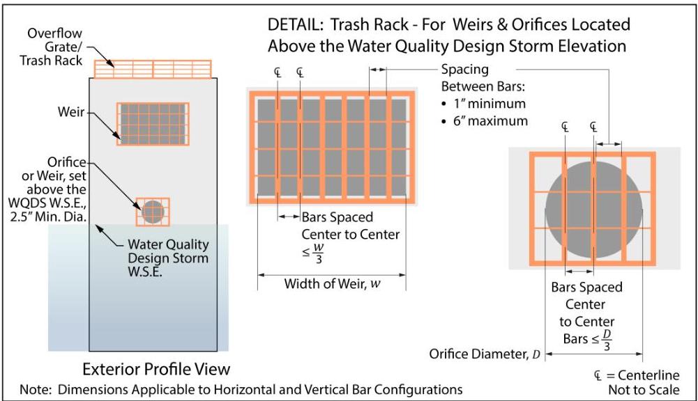
- An overflow grate is designed to prevent obstruction of the overflow structure. If an outlet structure has an overflow grate, the grate must comply with the following requirements:

☐ The overflow grate must be secured to the outlet structure but removable for emergencies and maintenance;
☐ The overflow grate spacing must be no greater than 2 inches across the smallest dimension; and
☐ The overflow g
PDF page 6, image 2
Mistral ID: img-3.jpeg. Extraction bundle(s): 2023_BMP_9_8_Small_Scale_Infiltration_Basins. Original page | Image file
Surrounding OCR excerpt:
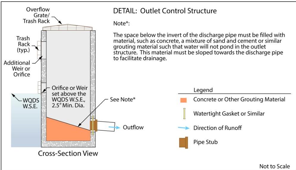
and cement, or similar grouting material, such that water will not pond in the outlet structure. This material must be sloped towards the discharge pipe to facilitate drainage, as shown in the detail below.

[OCR image]

- The minimum diameter of any overflow orifice is 2.5 inches.
PDF page 9, image 1
Mistral ID: img-4.jpeg. Extraction bundle(s): 2023_BMP_9_8_Small_Scale_Infiltration_Basins. Original page | Image file
Surrounding OCR excerpt:
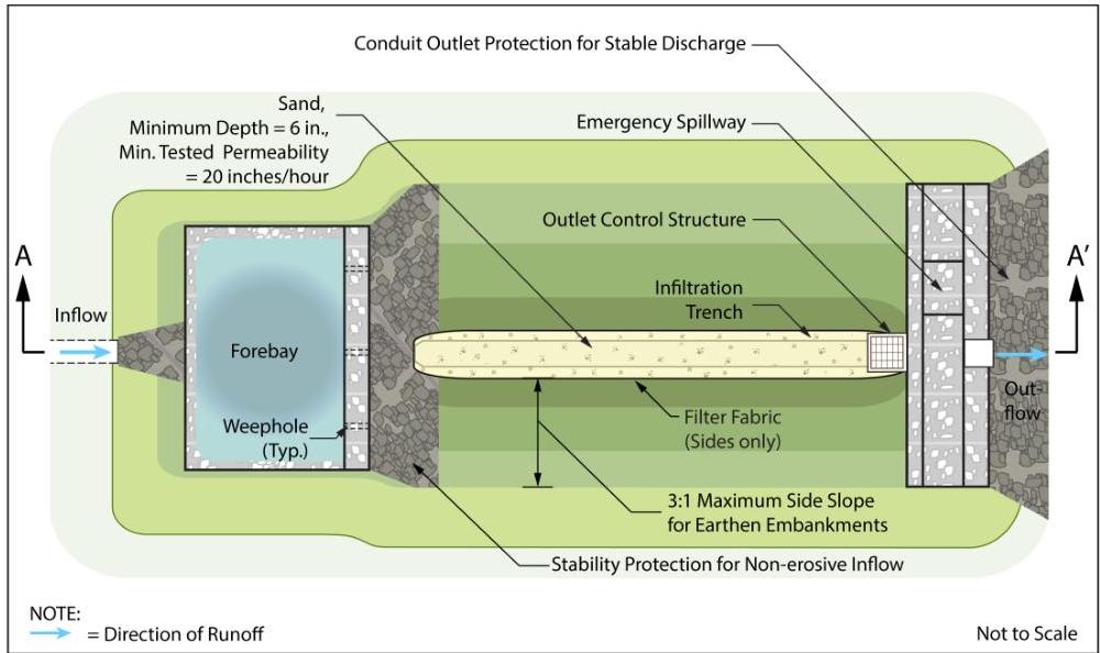
additional information on the design, operation and maintenance of the extended detention components, refer to Chapter 11.2: Extended Detention Basins.

[OCR image]
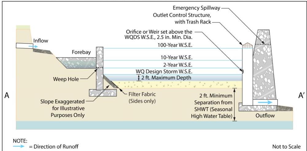
Small-scale Infiltration - Extended Detention Basin: Plan View

[OCR image]
Small-scale Infiltration - Extended Detention Basin: Profile View
PDF page 9, image 2
Mistral ID: img-5.jpeg. Extraction bundle(s): 2023_BMP_9_8_Small_Scale_Infiltration_Basins. Original page | Image file
Surrounding OCR excerpt:
n, operation and maintenance of the extended detention components, refer to Chapter 11.2: Extended Detention Basins.

[OCR image]
Small-scale Infiltration - Extended Detention Basin: Plan View

[OCR image]
Small-scale Infiltration - Extended Detention Basin: Profile View
PDF page 12, image 1
Mistral ID: img-6.jpeg. Extraction bundle(s): 2023_BMP_9_8_Small_Scale_Infiltration_Basins. Original page | Image file
Surrounding OCR excerpt:
[OCR image]
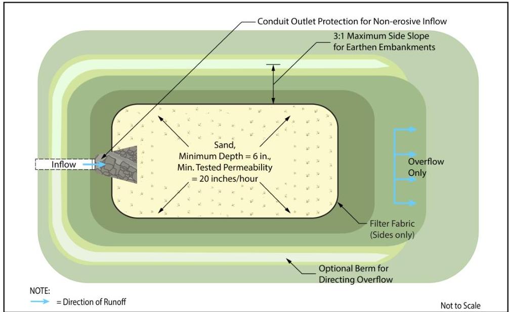
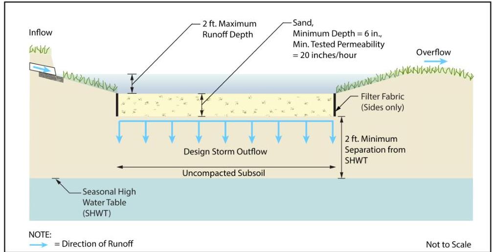
Small-Scale Surface Infiltration Basin – Plan View

[OCR image]
Small-Scale Surface Infiltration Basin – Profile View
PDF page 12, image 2
Mistral ID: img-7.jpeg. Extraction bundle(s): 2023_BMP_9_8_Small_Scale_Infiltration_Basins. Original page | Image file
Surrounding OCR excerpt:
[OCR image]
Small-Scale Surface Infiltration Basin – Plan View

[OCR image]
Small-Scale Surface Infiltration Basin – Profile View
PDF page 13, image 1
Mistral ID: img-8.jpeg. Extraction bundle(s): 2023_BMP_9_8_Small_Scale_Infiltration_Basins. Original page | Image file
Surrounding OCR excerpt:
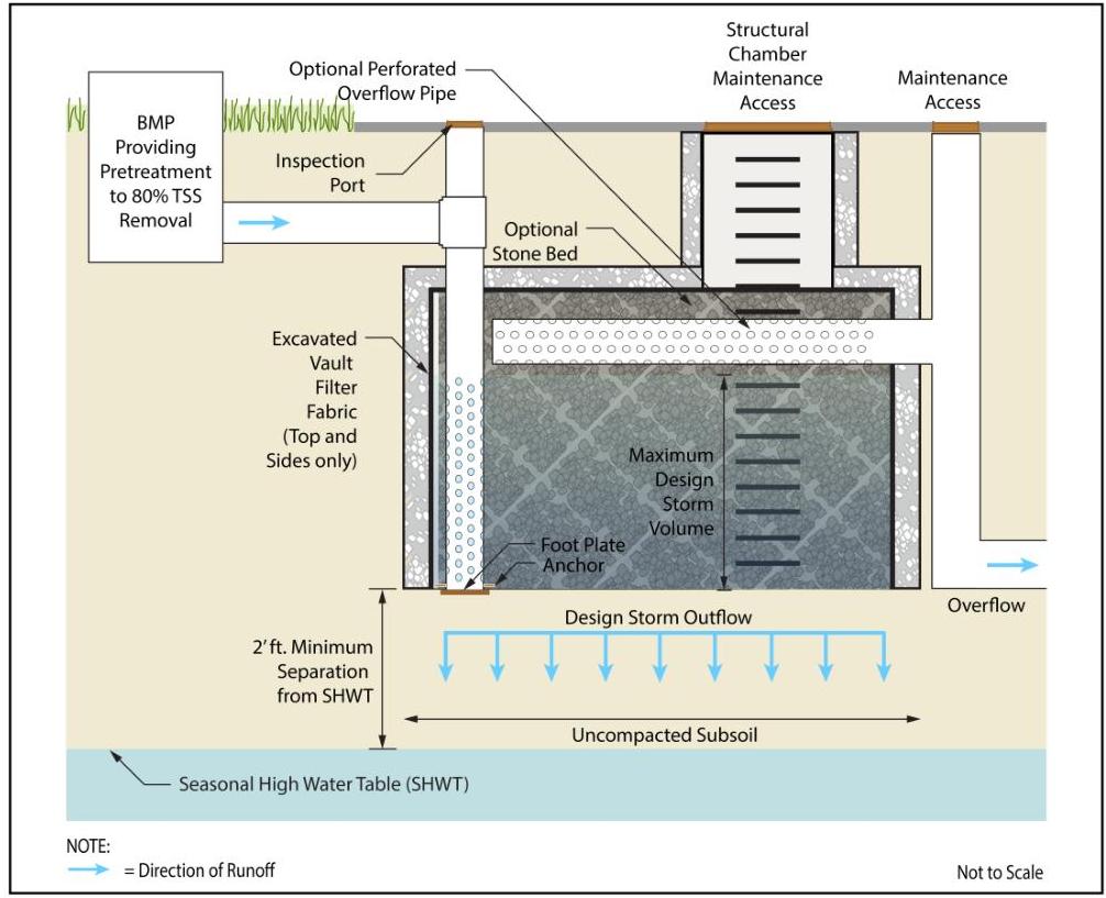
s depicted in the following illustration as an example, but it is not intended to limit the design configuration. Design criteria specific to this type of small-scale infiltration basin immediately follows.

[OCR image]

## Small-Scale Subsurface Infiltration Basin – Profile View

### Pretreatment for Small-Scale Subsurface Infiltration Basins

- Pretreatment is required on all small-scale subsurface infiltration basins.
- Roof runoff that directly discharges into the small-scale subsurface infiltration basin can be pretreated by leaf screens, first flush diverters or roof washers. For details of these pretreatment mea
PDF page 17, image 1
Mistral ID: img-9.jpeg. Extraction bundle(s): 2023_BMP_9_8_Small_Scale_Infiltration_Basins. Original page | Image file
Tables on the same PDF page: Table 5
Surrounding OCR excerpt:
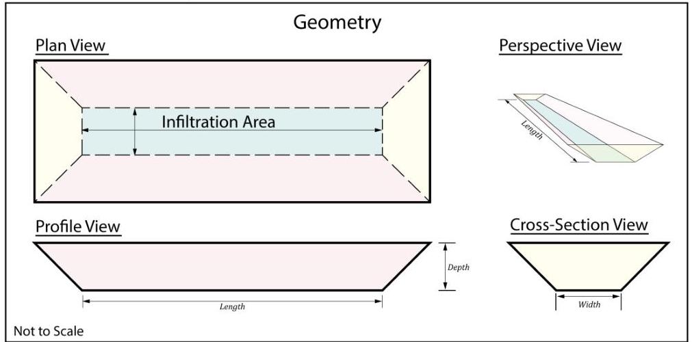
Example 1 - Geometry

[OCR image]

Summary Report:

|  Inflow Area = 43,560 sf,100.00% Impervious, Inflow Depth = 1.03"  |   |   |   |
| --- | --- | --- | --- |
|  Inflow = 2.66 cfs @ 1.13 hrs, Volume= 3,755 cf  |   |   |   |
|  Outflow = 0.19 cfs @ 1.89 hrs, Volume= 3,755 cf, Atten= 93%, Lag= 45.3 min  |   |   |   |
|  Discarded = 0.19 cfs @ 1.89 hrs, Volume= 3,755 cf  |   |   |   |
|  Routing by Stor-Ind method, Time Span= 0.00-48.00
PDF page 19, image 1
Mistral ID: img-10.jpeg. Extraction bundle(s): 2023_BMP_9_8_Small_Scale_Infiltration_Basins. Original page | Image file
Surrounding OCR excerpt:
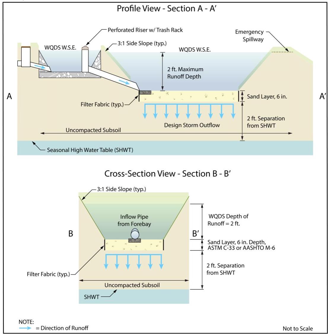
MPs. For this example, it is assumed the design meets the necessary groundwater mound requirements.

Illustrations for this example, exclusive of any refinements, are shown below and on the following page.

[OCR image]
PDF page 20, image 1
Mistral ID: img-11.jpeg. Extraction bundle(s): 2023_BMP_9_8_Small_Scale_Infiltration_Basins. Original page | Image file
Surrounding OCR excerpt:
[OCR image]
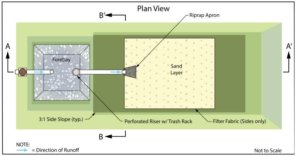
Example 1 – Plan View

Example 2: Using the following parameters, design a small-scale subsurface infiltration basin sized both for the WQDS and to provide groundwater recharge. Assume the site is not in an Urban Redevelopment Area. Assume pretreatment to provide 80% TSS removal is provided by an appropriate BMP or MTD.

Inflow Contributory Drainage Area = 1 ac
Existing Conditions:
Cover = Office Build
PDF page 24, image 1
Mistral ID: img-12.jpeg. Extraction bundle(s): 2023_BMP_9_8_Small_Scale_Infiltration_Basins. Original page | Image file
Tables on the same PDF page: Table 11
Surrounding OCR excerpt:
of infiltration period) |   |   |   |   |   |   |   |   |
|  16 | 8.15 | Δh(max) |  | Maximum groundwater mounding (beneath center of basin at end of infiltration period) |   |   |   |   |   |   |   |   |

[OCR image]

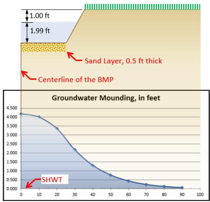
The maximum mounding height is 4.19 feet. In the Hantush Spreadsheet, the SHWT forms the x-axis. For this example, ground level is 10 ft above the SHWT, meaning, the top of the groundwater mounding will be 5.81 feet below the surface. As stated above, the surface of the basin sand layer is 2.99 ft below the adjacent ground surface. Therefore, the top of the groundwater mounding is 2.82 ft below the to