Extracted images: Subsurface Gravel Wetlands (Non-GI)
Printed revision: March 2021.
Back to source | Original PDF | Image metadata
Original Mistral crops are preserved byte for byte. A crop can be a figure, table, equation, or other visual; no visual content is inferred as a numerical rule. Record and table associations use the same PDF page unless a direct image placeholder is identified. Nearby OCR excerpts are context, not verified captions.
PDF page 1, image 1
Mistral ID: img-0.jpeg. Extraction bundle(s): 2023_BMP_11_5_Subsurface_Gravel_Wetlands. Original page | Image file
Tables on the same PDF page: Table 1
Surrounding OCR excerpt:
# 11.5 SUBSURFACE GRAVEL WETLANDS

[OCR image]

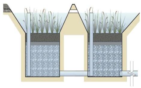
Subsurface gravel wetlands are a stormwater management system designed to maximize the removal of pollutants from stormwater runoff; the system is a combination of a surface marsh and a subsurface gravel bed. Pollutants are treated through settling, by both uptake and filtration by vegetation and by chemical transformation in the subsurface bed, specifically denitrification. Both the total suspended so
PDF page 6, image 1
Mistral ID: img-1.jpeg. Extraction bundle(s): 2023_BMP_11_5_Subsurface_Gravel_Wetlands. Original page | Image file
Surrounding OCR excerpt:
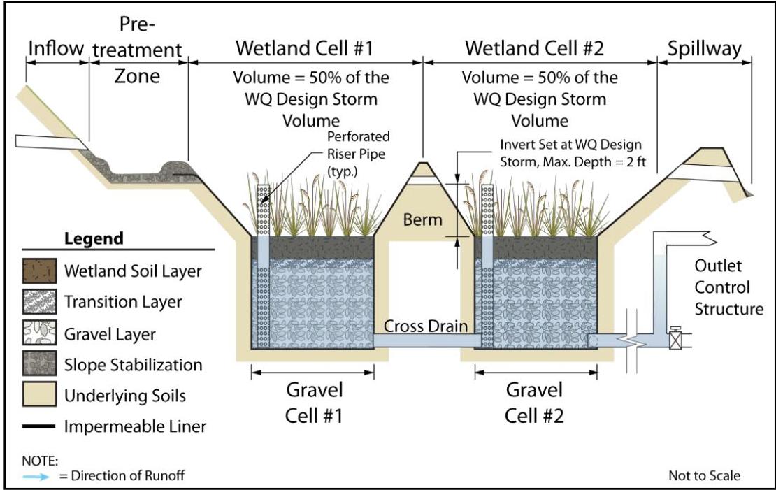
ter runoff through the gravel wetland system. For more information on each component, refer to the Subsurface Gravel Wetland Components section of this chapter, beginning on Page 10.

## Initial Equilibrium

[OCR image]

Between storm events, runoff from the previous storm is only detained in the gravel cells; subsurface gravel wetlands are not intended to store stormwater runoff in any surface component for longer than 72 hours after the end of a storm event.

## Stage 1 - Onset of Runoff

[OCR image]

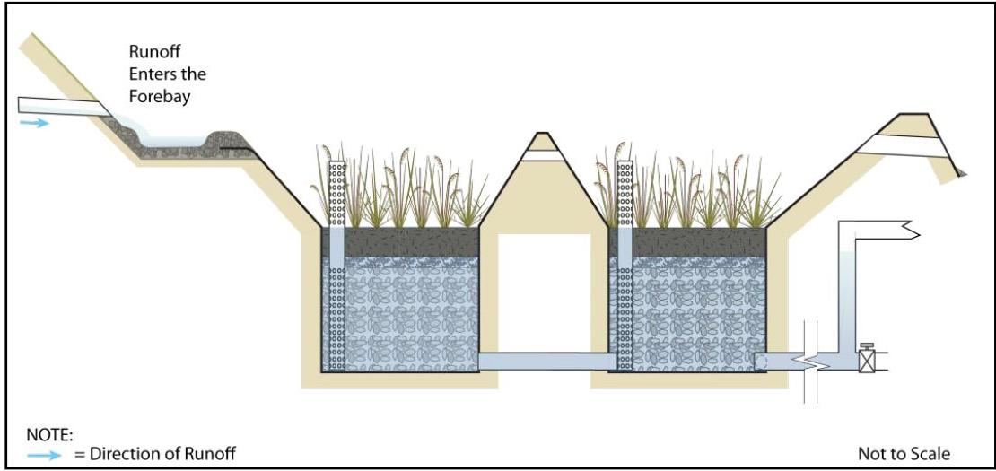
Runoff enters the pretreatment zone, in this case, a forebay.
PDF page 6, image 2
Mistral ID: img-2.jpeg. Extraction bundle(s): 2023_BMP_11_5_Subsurface_Gravel_Wetlands. Original page | Image file
Surrounding OCR excerpt:
ed in the gravel cells; subsurface gravel wetlands are not intended to store stormwater runoff in any surface component for longer than 72 hours after the end of a storm event.

## Stage 1 - Onset of Runoff

[OCR image]

Runoff enters the pretreatment zone, in this case, a forebay.
PDF page 7, image 1
Mistral ID: img-3.jpeg. Extraction bundle(s): 2023_BMP_11_5_Subsurface_Gravel_Wetlands. Original page | Image file
Surrounding OCR excerpt:
[OCR image]
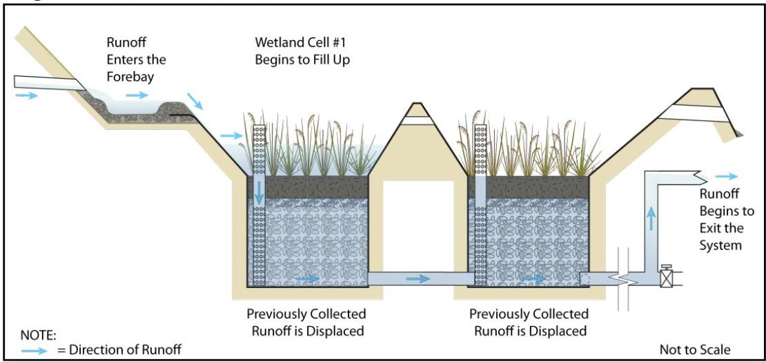
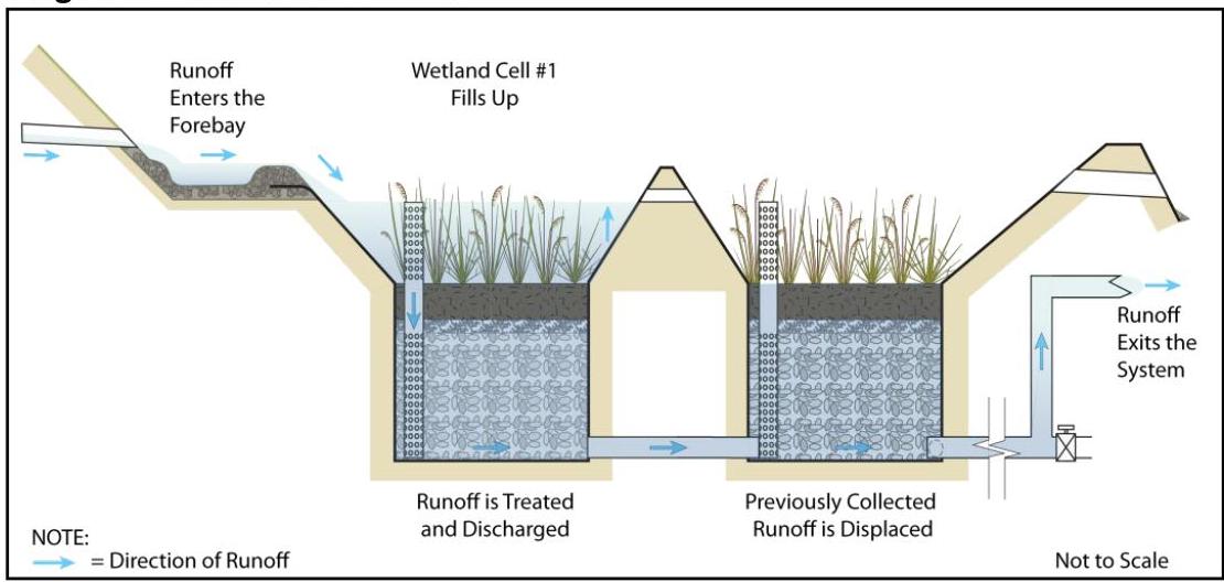
Stage 2 – Runoff Enters Wetland Cell #1

Runoff fills the forebay and begins to flow into Wetland Cell #1. As Wetland Cell #1 fills, runoff is discharged through the perforated riser pipe into Gravel Cell #1. The runoff from the previous storm event only begins to discharge through the outlet structure when it is displaced by the new flow.

[OCR image]
Stage 3 – Wetland Cell #1 Fills

As t
PDF page 7, image 2
Mistral ID: img-4.jpeg. Extraction bundle(s): 2023_BMP_11_5_Subsurface_Gravel_Wetlands. Original page | Image file
Surrounding OCR excerpt:
noff is discharged through the perforated riser pipe into Gravel Cell #1. The runoff from the previous storm event only begins to discharge through the outlet structure when it is displaced by the new flow.

[OCR image]
Stage 3 – Wetland Cell #1 Fills

As the rain event continues, Gravel Cell #1 begins to discharge into Gravel Cell #2 through the subsurface cross drain. The continuous inflow of runoff into the system forces the flow from Gravel Cell #2 to discharge through the outlet structure.
PDF page 8, image 1
Mistral ID: img-5.jpeg. Extraction bundle(s): 2023_BMP_11_5_Subsurface_Gravel_Wetlands. Original page | Image file
Surrounding OCR excerpt:
[OCR image]
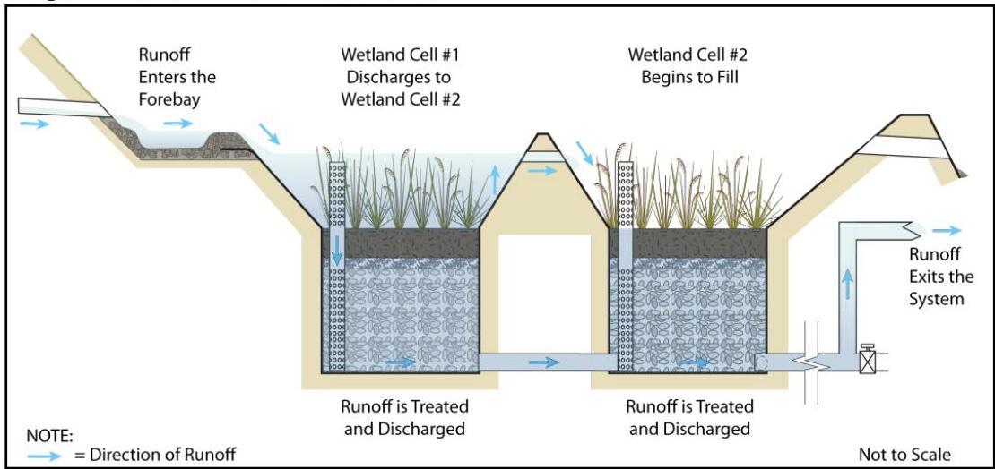
Stage 4 - Runoff Enters Wetland Cell #2

As runoff continues to enter the system, it discharges from Wetland Cell #1 to Wetland Cell #2 through the surface cross drain, and it continues to discharge from Gravel Cell #1 to Gravel Cell #2 through the subsurface cross drain. As Wetland Cell #2 fills, runoff begins to discharge into Gravel Cell #2 through the perforated riser pipe in Wetland Cell #2. This r
PDF page 8, image 2
Mistral ID: img-6.jpeg. Extraction bundle(s): 2023_BMP_11_5_Subsurface_Gravel_Wetlands. Original page | Image file
Surrounding OCR excerpt:
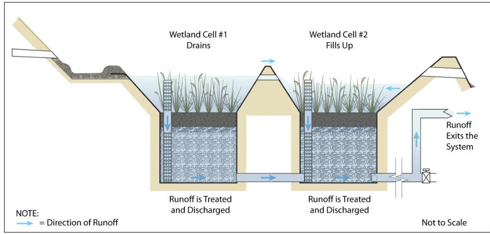
This runoff will travel horizontally through the gravel in Gravel Cell #2 prior to being forced out of the system through the outlet structure by runoff from Gravel Cell #1 discharging into Gravel Cell #2.

[OCR image]
Stage 5 – Wetland Cell #2 Fills

At this stage, which is some time after the end of the rain event, runoff no longer enters the system. Runoff in Wetland Cell #1 discharges to either Gravel Cell #1, through the perforated riser pipe, or to Wetland Cell #2, through the surface cross drain. Runoff in Wetland Cell #2 discharges to Gravel Cell #2 through the perforated riser pipe. Runoff continues to discha
PDF page 9, image 1
Mistral ID: img-7.jpeg. Extraction bundle(s): 2023_BMP_11_5_Subsurface_Gravel_Wetlands. Original page | Image file
Surrounding OCR excerpt:
[OCR image]
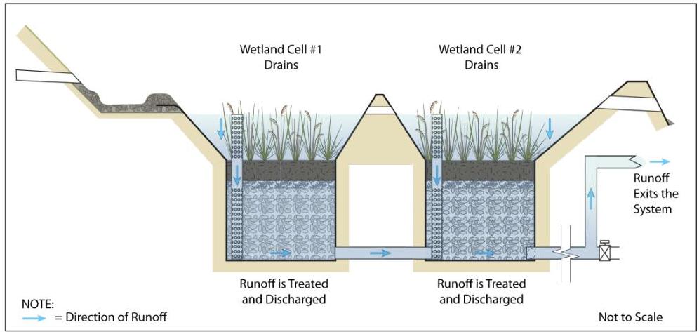
Stage 6 – Runoff Exits the System as the Wetland Cells Drain

Discharge of treated runoff through the outlet structure continues as the runoff that is stored in both of the wetland cells discharges into the gravel cells.

[OCR image]
Stage 7 - Equilibrium is Restored

After all of stored runoff in the wetland cells is discharged to the gravel cells, outflow from the outlet structure ceases
PDF page 9, image 2
Mistral ID: img-8.jpeg. Extraction bundle(s): 2023_BMP_11_5_Subsurface_Gravel_Wetlands. Original page | Image file
Surrounding OCR excerpt:
ff Exits the System as the Wetland Cells Drain

Discharge of treated runoff through the outlet structure continues as the runoff that is stored in both of the wetland cells discharges into the gravel cells.

[OCR image]
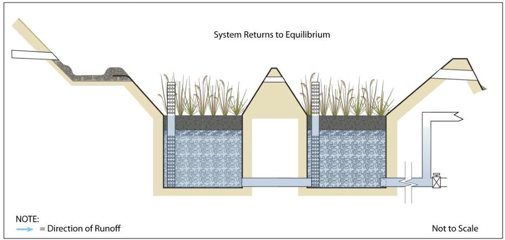
Stage 7 - Equilibrium is Restored

After all of stored runoff in the wetland cells is discharged to the gravel cells, outflow from the outlet structure ceases in the absence of displacement from new runoff. The system returns to equilibrium.
PDF page 10, image 1
Mistral ID: img-9.jpeg. Extraction bundle(s): 2023_BMP_11_5_Subsurface_Gravel_Wetlands. Original page | Image file
Surrounding OCR excerpt:
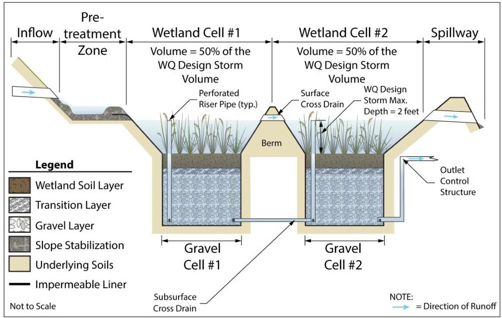
rface wetland cell, two subsurface gravel cells connected by a subsurface cross drain, two perforated riser pipes connecting each of the wetland cells to the gravel cells below them and an outlet structure.

[OCR image]

Profile View – General Components

Each surface wetland cell must be connected by a cross drain and sized to store 50% of the WQDS volume. The strategy (forebay, vegetative filter strip, or MTD) selected for use in the pretreatment zone must be sized separately from the gravel wetland system.

The transition layer between the wetland soil and the gravel cells is required to prevent the finer portion of
PDF page 11, image 1
Mistral ID: img-10.jpeg. Extraction bundle(s): 2023_BMP_11_5_Subsurface_Gravel_Wetlands. Original page | Image file
Surrounding OCR excerpt:
where the native soils are sufficiently impermeable, the liner may be omitted provided that the system has the required separation from the SHWT.

[OCR image]
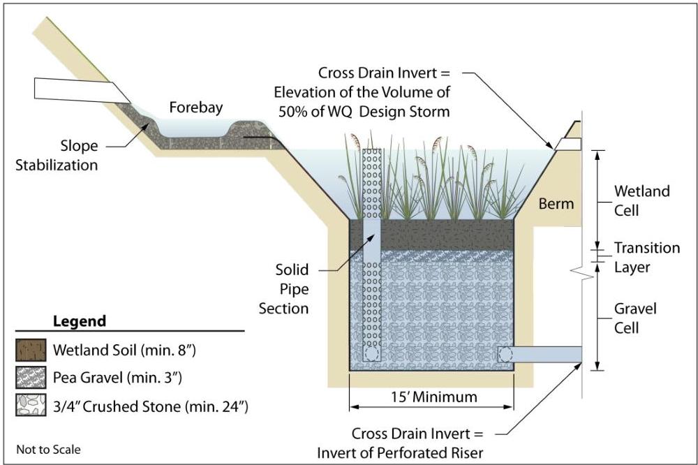
Detailed Profile of Wetland Cell #1 and Gravel Cell #1

The illustration above shows a closer view of the first half of the subsurface gravel wetland system. Runoff enters the system through the forebay; from there, it enters Wetland Cell #1. The riser pipe in the wetland cell has perforations up to the elevation of the WQDS. Flows up to this elevation are slowly discharged into Gravel Cell #1; flows i
PDF page 12, image 1
Mistral ID: img-11.jpeg. Extraction bundle(s): 2023_BMP_11_5_Subsurface_Gravel_Wetlands. Original page | Image file
Surrounding OCR excerpt:
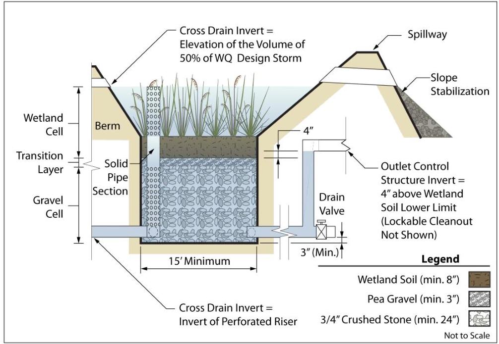
# Detailed Profile of Wetland Cell #2 and Gravel Cell #2

[OCR image]

This illustration shows a closer view of the second half of the subsurface gravel wetland system. As shown in the previous illustration, runoff up to the elevation of $\frac{1}{2}$ the WQDS volume is temporarily stored in Wetland Cell #1. Flows in excess of this elevation enter Wetland Cell #2 through the cross drain. As with Wetland Cell #1, there is another riser pipe in Wetland Cell #2, which also
PDF page 13, image 1
Mistral ID: img-12.jpeg. Extraction bundle(s): 2023_BMP_11_5_Subsurface_Gravel_Wetlands. Original page | Image file
Surrounding OCR excerpt:
[OCR image]
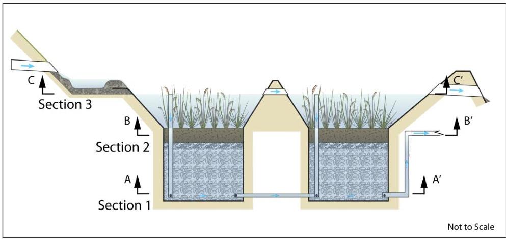
Guide to Sections in Plan View

The above illustration depicts the same gravel wetland system divided into three horizontal sections, each at different elevations. The following three illustrations each focus on a specific section of the gravel wetland system, as shown above.

[OCR image]
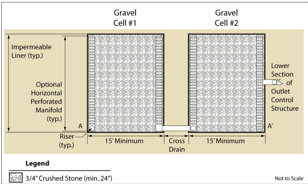
Section 1 Plan View – Gravel Cells #1 and #2

The above illustration depicts a plan view of the gra
PDF page 13, image 2
Mistral ID: img-13.jpeg. Extraction bundle(s): 2023_BMP_11_5_Subsurface_Gravel_Wetlands. Original page | Image file
Surrounding OCR excerpt:
gravel wetland system divided into three horizontal sections, each at different elevations. The following three illustrations each focus on a specific section of the gravel wetland system, as shown above.

[OCR image]
Section 1 Plan View – Gravel Cells #1 and #2

The above illustration depicts a plan view of the gravel cells, which shows an optional horizontal perforated manifold; the manifold is intended to help distribute the flow through the gravel cells in systems where the width of the gravel cells is wide enough to impede dispersal.

The above illustration also shows the required 15-foot minimum length in each
PDF page 14, image 1
Mistral ID: img-14.jpeg. Extraction bundle(s): 2023_BMP_11_5_Subsurface_Gravel_Wetlands. Original page | Image file
Surrounding OCR excerpt:
um inflow rate; this is necessary to address potential clogging and to ensure that the pipes do not act as a hydraulic control. The system must be designed to drain the WQDS volume between 24 and 48 hours.

[OCR image]
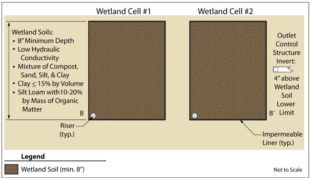
Section 2 Plan View – Wetland Soil Layer in Both Cells

This illustration shows the wetland soil layer at a distance of 4 inches above the transition layer. This elevation is important because it is the elevation at which the invert of the primary outlet must be located. At this elevation, the primary outlet maintains the water level at 4 inches above the bottom of the wetland soil; continuous inundati
PDF page 15, image 1
Mistral ID: img-15.jpeg. Extraction bundle(s): 2023_BMP_11_5_Subsurface_Gravel_Wetlands. Original page | Image file
Surrounding OCR excerpt:
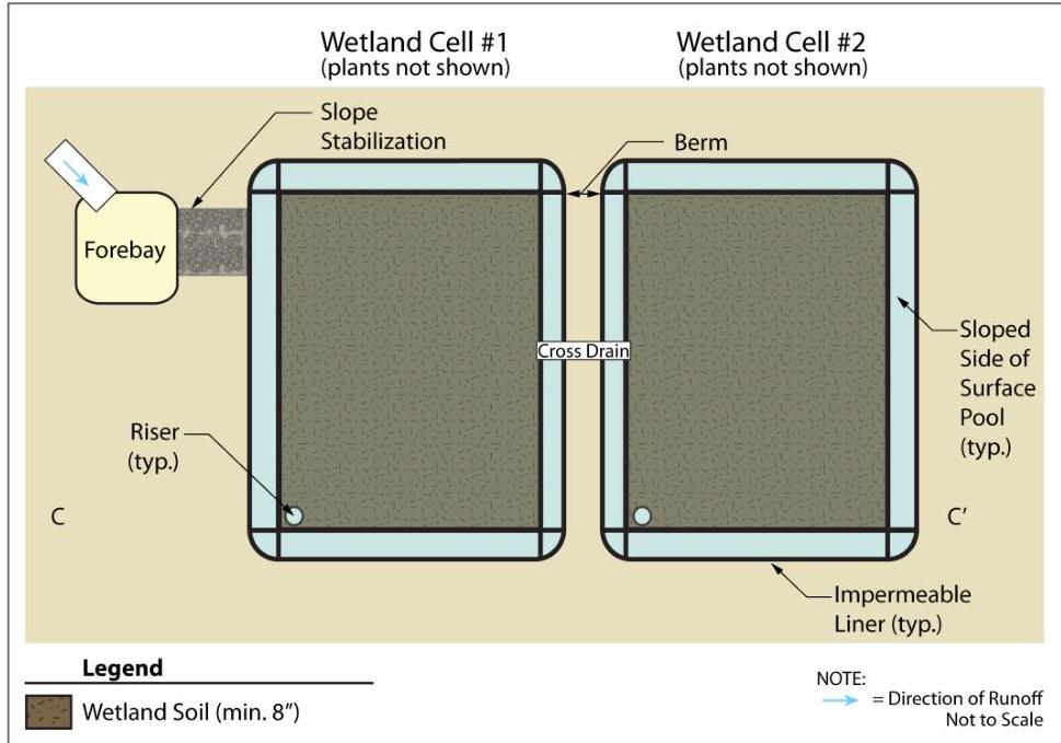
# Section 3 Plan View – Wetland Cells at the Surface Cross Drain

[OCR image]

This illustration depicts the top of the gravel wetland system looking down through the wetland cells at the elevation of the surface cross drain; the vegetation has been omitted to better show the other components. As previously shown, runoff enters the system through the forebay and then flows into Wetland Cell #1. All flows up to the elevation of the WQDS volume are discharged into Gravel Cell #1 t