Extracted images: Standard Constructed Wetlands (Large-Scale GI)
Printed revision: January 2026.
Back to source | Original PDF | Image metadata
Original Mistral crops are preserved byte for byte. A crop can be a figure, table, equation, or other visual; no visual content is inferred as a numerical rule. Record and table associations use the same PDF page unless a direct image placeholder is identified. Nearby OCR excerpts are context, not verified captions.
PDF page 1, image 1
Mistral ID: img-0.jpeg. Extraction bundle(s): 2026_BMP_10_4_Standard_Constructed_Wetlands. Original page | Image file
Tables on the same PDF page: Table 1
Surrounding OCR excerpt:
# 10.4 STANDARD CONSTRUCTED WETLANDS

[OCR image]

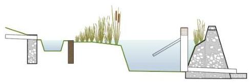
Standard constructed wetlands are stormwater management systems designed to maximize the removal of pollutants from stormwater runoff and may be used to address the quantity impacts of land development. Flow is directed through an engineered, open marsh system where pollutants are removed through settling and vegetative uptake/filtration. The total suspended solids (TSS) removal rate is 90%.

|  N.J.A.
PDF page 3, image 1
Mistral ID: img-1.jpeg. Extraction bundle(s): 2026_BMP_10_4_Standard_Constructed_Wetlands. Original page | Image file

Surrounding OCR excerpt:
# Applications

[OCR image]

Pursuant to N.J.A.C. 7:8-5.2(a)(2), the minimum design and performance standards for groundwater recharge, stormwater runoff quality and stormwater runoff quantity at N.J.A.C. 7:8- 5.4, 5.5 and 5.6 shall be met by incorporating green infrastructure in accordance with N.J.A.C. 7:8-5.3. Pursuant to N.J.A.C. 7:8-5.3(c), large-scale green infrastructure BMPs may only be used to satisfy the stormwater runof
PDF page 3, image 2
Mistral ID: img-2.jpeg. Extraction bundle(s): 2026_BMP_10_4_Standard_Constructed_Wetlands. Original page | Image file

Surrounding OCR excerpt:
orating green infrastructure in accordance with N.J.A.C. 7:8-5.3. Pursuant to N.J.A.C. 7:8-5.3(c), large-scale green infrastructure BMPs may only be used to satisfy the stormwater runoff quantity standards.

[OCR image]

Standard constructed wetlands may be designed to reduce peak runoff rates when designed as an on-line system. Regardless of the design storm chosen, standard constructed wetlands must be designed for stability and capacity in accordance with the Standards for Soil Erosion and Sediment Control in New Jersey.

Only if a waiver or variance from the green infrastructure requirements of N.J.A.C. 7:8-5.3 is
PDF page 6, image 1
Mistral ID: img-3.jpeg. Extraction bundle(s): 2026_BMP_10_4_Standard_Constructed_Wetlands. Original page | Image file
Surrounding OCR excerpt:
# Hooded and Reverse-Slope Outlet Structures

[OCR image]

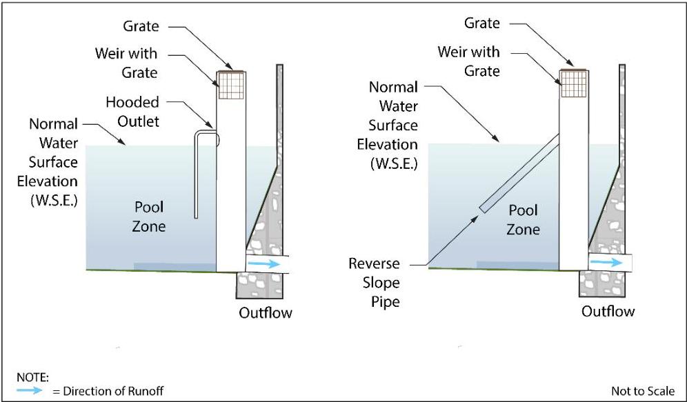
- The invert of the lowest stormwater quantity control outlet must be set at or above the normal water surface elevation in on-line systems.
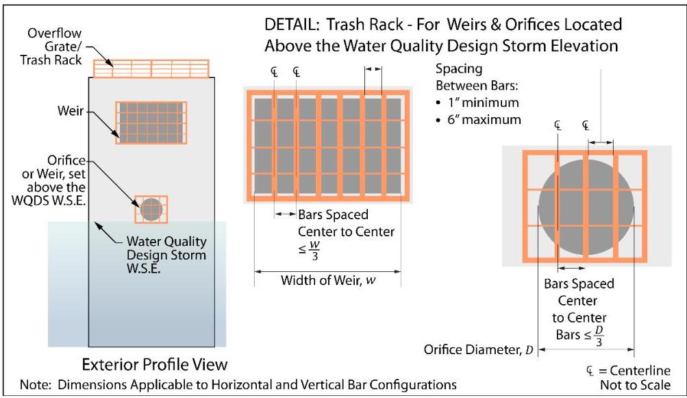
- Trash racks must be installed at the intake to the outlet structure. They must also be designed to avoid acting as the hydraulic control for the system, and they must meet the following criteria, as required by N.J.A.C. 7:8-5.2(i)2 and 6.2(a), and the detail on
PDF page 7, image 1
Mistral ID: img-4.jpeg. Extraction bundle(s): 2026_BMP_10_4_Standard_Constructed_Wetlands. Original page | Image file
Surrounding OCR excerpt:
[OCR image]

- An overflow grate is designed to prevent obstruction of the overflow structure. If an outlet structure has an overflow grate, the grate must comply with the following requirements:

☐ The overflow grate must be secured to the outlet structure but removable for emergencies and maintenance;
☐ The overflow grate spacing must be no greater than 2 inches across the smallest dimension; and
☐ The overflow g
PDF page 7, image 2
Mistral ID: img-5.jpeg. Extraction bundle(s): 2026_BMP_10_4_Standard_Constructed_Wetlands. Original page | Image file
Surrounding OCR excerpt:
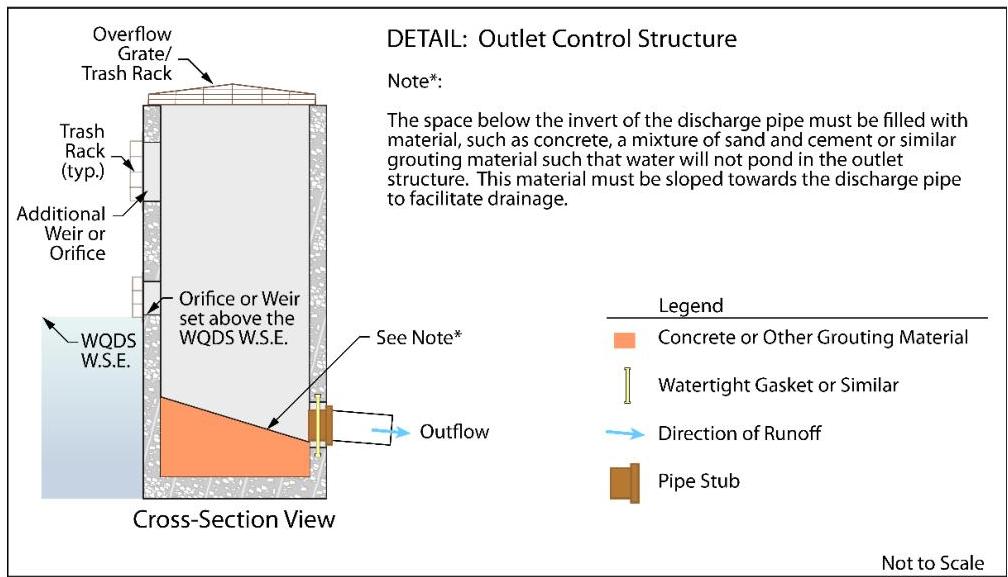
and cement, or similar grouting material, such that water will not pond in the outlet structure. This material must be sloped towards the discharge pipe to facilitate drainage, as shown in the detail below.

[OCR image]
PDF page 10, image 1
Mistral ID: img-6.jpeg. Extraction bundle(s): 2026_BMP_10_4_Standard_Constructed_Wetlands. Original page | Image file
Surrounding OCR excerpt:
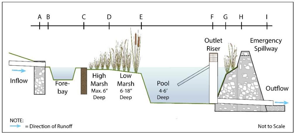
etland, the allocation of the WQDS runoff volume is shown. The illustrations depict possible configurations and flow paths and are not intended to limit the design.

## Category 1: Pond Constructed Wetlands

[OCR image]
Pond Constructed Wetlands - Profile View

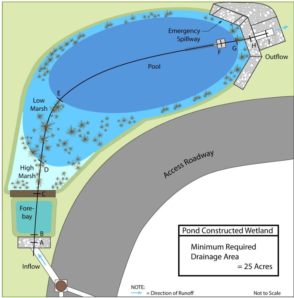
The illustration above shows the various components comprising a standard constructed wetland system from the pond category. Following the direction that runoff would take through the BMP; flow enters the system at A and then flows into the forebay spanning B to C. From the forebay, runoff flows over the spillway at C into the high marsh zone; it then enters the
PDF page 11, image 1
Mistral ID: img-7.jpeg. Extraction bundle(s): 2026_BMP_10_4_Standard_Constructed_Wetlands. Original page | Image file
Tables on the same PDF page: Table 3
Surrounding OCR excerpt:
[OCR image]
Pond Constructed Wetlands - Plan View

The table below shows the design criteria specific to pond constructed wetlands; for additional design criteria, refer to the Basic Requirements section of this chapter, beginning on Page 3.

|  Pond Constructed Wetlands Design Criteria  |   |
| --- | --- |
|  Minimum Drainage Area | 25 Acres  |
|  Standing Water Depth: High Marsh Zone | Maximum 6 Inches  |
|  Stan
PDF page 12, image 1
Mistral ID: img-8.jpeg. Extraction bundle(s): 2026_BMP_10_4_Standard_Constructed_Wetlands. Original page | Image file
Surrounding OCR excerpt:
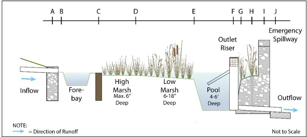
# Category 2: Marsh Constructed Wetlands

[OCR image]
Marsh Constructed Wetlands - Profile View

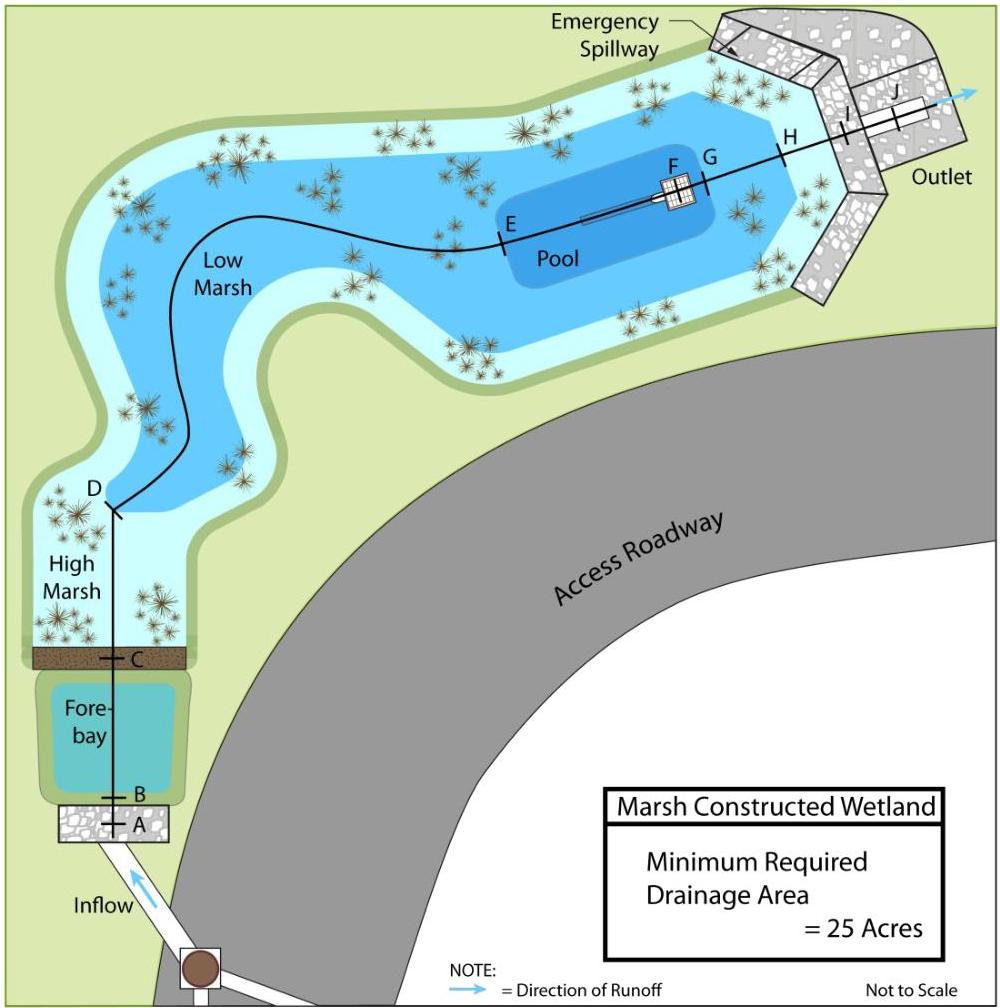
The illustration above shows the various components comprising a standard constructed wetland system from the marsh category. As with pond constructed wetlands, the minimum inflow drainage area is 25 acres. In this illustration, again, stormwater runoff enters the system at A and then flows into the forebay spanning B to C. From the forebay, runoff flows over t
PDF page 13, image 1
Mistral ID: img-9.jpeg. Extraction bundle(s): 2026_BMP_10_4_Standard_Constructed_Wetlands. Original page | Image file
Tables on the same PDF page: Table 4
Surrounding OCR excerpt:
[OCR image]
Marsh Constructed Wetlands - Plan View

The table below shows the design criteria specific to marsh constructed wetlands; for additional design criteria, refer to the Basic Requirements section of this chapter, beginning on Page 3.

|  Marsh Constructed Wetland Design Criteria  |   |
| --- | --- |
|  Minimum Drainage Area | 25 Acres  |
|  Standing Water Depth: High Marsh Zone | Maximum 6 inches  |
|  St
PDF page 14, image 1
Mistral ID: img-10.jpeg. Extraction bundle(s): 2026_BMP_10_4_Standard_Constructed_Wetlands. Original page | Image file
Surrounding OCR excerpt:
# Category 3: Extended Detention Constructed Wetlands

[OCR image]
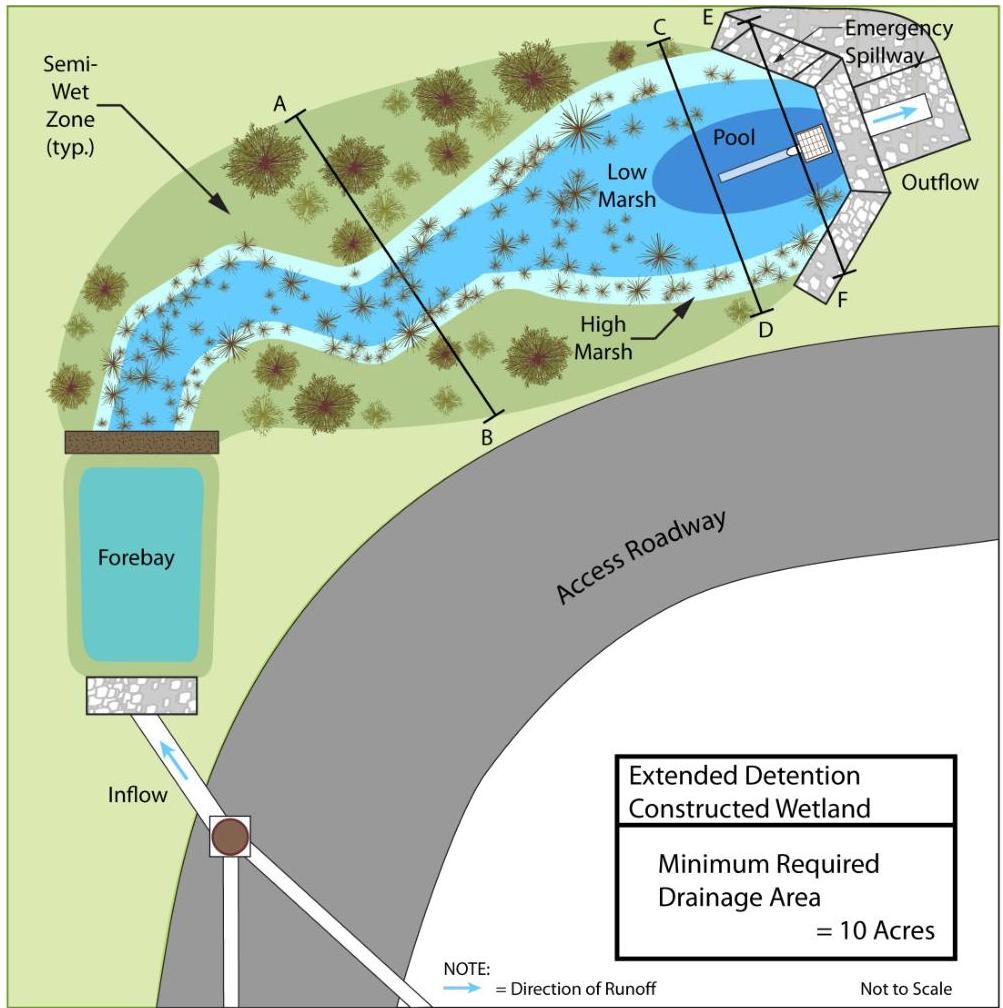
Extended Detention Constructed Wetlands - Plan View

The illustration above shows the various components comprising a standard constructed wetland system from the extended detention category, for which a profile view taken along the centerline would look almost the same as a marsh constructed wetlands. Following the direction that stormwater runoff would take through the BMP; runoff enters the forebay
PDF page 15, image 1
Mistral ID: img-11.jpeg. Extraction bundle(s): 2026_BMP_10_4_Standard_Constructed_Wetlands. Original page | Image file
Surrounding OCR excerpt:
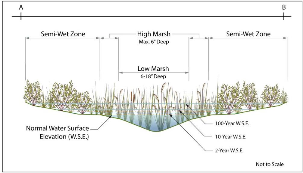
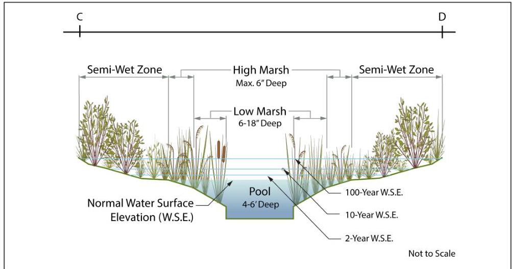
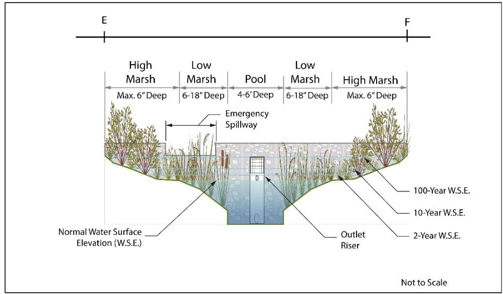
E-F depicts the view taken at the front face of the outlet riser structure. In these illustrations, the semi-wet zone has been sized to contain the volume of runoff generated by the 100-year design storm.

[OCR image]
Extended Detention Constructed Wetlands – Cross-section View A-B

[OCR image]
Extended Detention Constructed Wetlands – Cross-section View C-D

Page 15
PDF page 15, image 2
Mistral ID: img-12.jpeg. Extraction bundle(s): 2026_BMP_10_4_Standard_Constructed_Wetlands. Original page | Image file
Surrounding OCR excerpt:
tions, the semi-wet zone has been sized to contain the volume of runoff generated by the 100-year design storm.

[OCR image]
Extended Detention Constructed Wetlands – Cross-section View A-B

[OCR image]
Extended Detention Constructed Wetlands – Cross-section View C-D

Page 15
PDF page 16, image 1
Mistral ID: img-13.jpeg. Extraction bundle(s): 2026_BMP_10_4_Standard_Constructed_Wetlands. Original page | Image file
Tables on the same PDF page: Table 5
Surrounding OCR excerpt:
# Extended Detention Constructed Wetlands – Cross-section View E-F

[OCR image]

The table below shows the design criteria specific to marsh constructed wetlands; for additional design criteria, refer to the Basic Requirements section of this chapter, beginning on Page 3.

|  Extended Detention Constructed Wetland Design Criteria  |   |
| --- | --- |
|  Minimum Drainage Area | 10 Acres  |
|  Standing Water Depth: High Marsh Zone | Maximum 6 Inches  |
|  Standing Water Depth: Low M
PDF page 17, image 1
Mistral ID: img-14.jpeg. Extraction bundle(s): 2026_BMP_10_4_Standard_Constructed_Wetlands. Original page | Image file
Surrounding OCR excerpt:
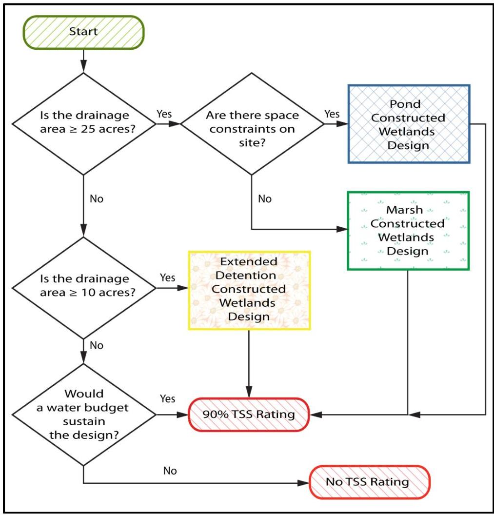
low is available; a water budget must be included in this analysis. For more information on how to complete a water budget see the Water Budget Manual at http://www.nj.gov/dep/landuse/download/mit_011.pdf.

[OCR image]