Extracted images: Extended Detention Basins (Non-GI)
Printed revision: January 2026.
Back to source | Original PDF | Image metadata
Original Mistral crops are preserved byte for byte. A crop can be a figure, table, equation, or other visual; no visual content is inferred as a numerical rule. Record and table associations use the same PDF page unless a direct image placeholder is identified. Nearby OCR excerpts are context, not verified captions.
PDF page 1, image 1
Mistral ID: img-0.jpeg. Extraction bundle(s): 2026_BMP_11_2_Extended_Detention_Basins. Original page | Image file
Tables on the same PDF page: Table 1
Surrounding OCR excerpt:
# 11.2 EXTENDED DETENTION BASINS (NON-GI)

[OCR image]

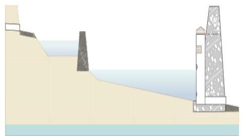
An extended detention basin is a stormwater management system that temporarily stores and attenuates stormwater runoff. In addition, extended detention basins provide pollutant treatment for runoff from the Water Quality Design Storm through settling. When designed in accordance with this chapter, the total suspended solids (TSS) removal rate is 40 - 60%, depending on the duration of runoff detention.
PDF page 2, image 1
Mistral ID: img-1.jpeg. Extraction bundle(s): 2026_BMP_11_2_Extended_Detention_Basins. Original page | Image file

Surrounding OCR excerpt:
f green infrastructure.

Extended detention basins must have a maintenance plan and must be reflected in a deed notice recorded in the county clerk's office to prevent alteration or removal.

# Applications

[OCR image]

Only if a waiver or variance form the green infrastructure requirements of N.J.A.C. 7:8-5.3 is obtained may extended detention basins that are designed to convey storm events larger than the Water Quality Design Storm be used to meet the stormwater runoff quantity requirements. Additionally, regardless of the design storm chosen, all extended detention basins must be designed for stability in accordanc
PDF page 2, image 2
Mistral ID: img-2.jpeg. Extraction bundle(s): 2026_BMP_11_2_Extended_Detention_Basins. Original page | Image file

Surrounding OCR excerpt:
st be designed for stability in accordance with the Standards for Soil Erosion and Sediment Control in New Jersey, as required by N.J.A.C. 7:8 and provided the aforementioned waiver or variance is approved.

[OCR image]

Only if a waiver or variance from the green infrastructure requirements of N.J.A.C. 7:8-5.3 is obtained may extended detention basins be awarded a TSS removal rate of 40-60%. To merit the approved TSS removal rate of 40-60%, extended detention basins must also treat the Water Quality Design Storm (WQDS) and be designed in accordance with all of the design criteria below.

# Design Criteria

## Basic Re
PDF page 4, image 1
Mistral ID: img-3.jpeg. Extraction bundle(s): 2026_BMP_11_2_Extended_Detention_Basins. Original page | Image file
Surrounding OCR excerpt:
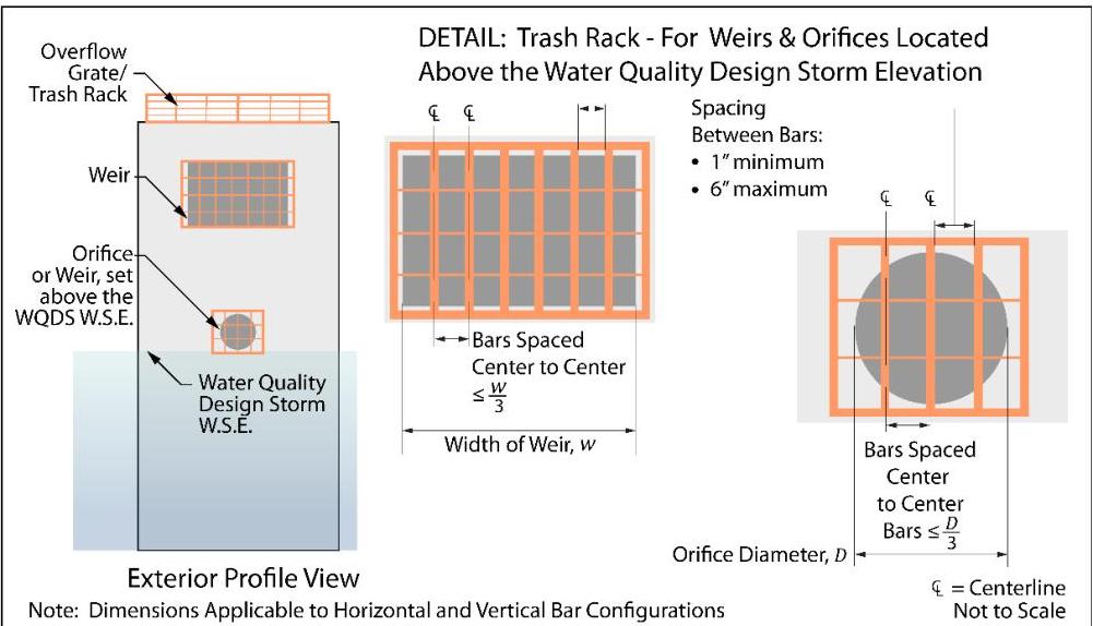
ly affect the hydraulic performance of the outlet pipe or structure;
☐ Constructed of rigid, durable and corrosion-resistant material; and
☐ Designed to withstand a perpendicular live loading of 300 lbs/sf.

[OCR image]
PDF page 5, image 1
Mistral ID: img-4.jpeg. Extraction bundle(s): 2026_BMP_11_2_Extended_Detention_Basins. Original page | Image file
Surrounding OCR excerpt:
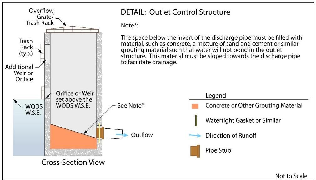
and cement, or similar grouting material, such that water will not pond in the outlet structure. This material must be sloped towards the discharge pipe to facilitate drainage, as shown in the detail below.

[OCR image]

- Blind connections to down-gradient facilities are prohibited. Any connection to down-gradient stormwater management facilities must include access points such as inspections ports and manholes, for visual inspection and maintenance, as appropriate, to prevent blockage of flow and ensure operation as intended. All entrance points must adhere to all State, County and municipal safety standards such as
PDF page 7, image 1
Mistral ID: img-5.jpeg. Extraction bundle(s): 2026_BMP_11_2_Extended_Detention_Basins. Original page | Image file
Surrounding OCR excerpt:
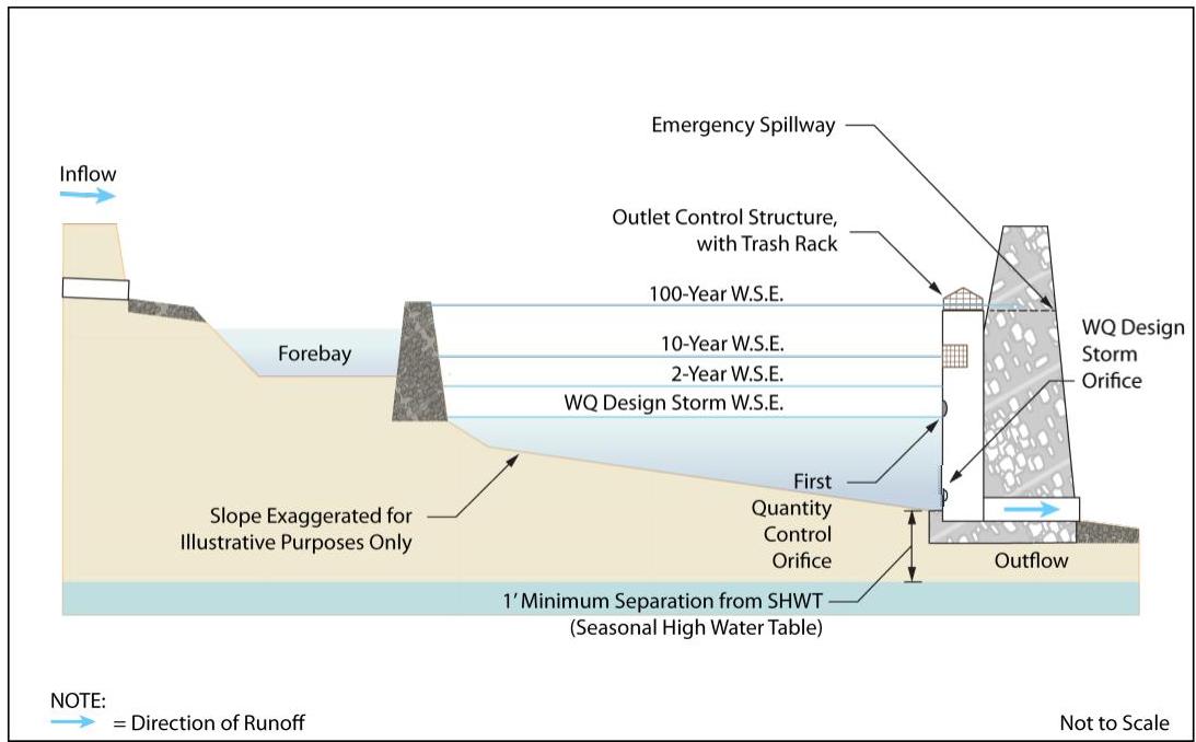
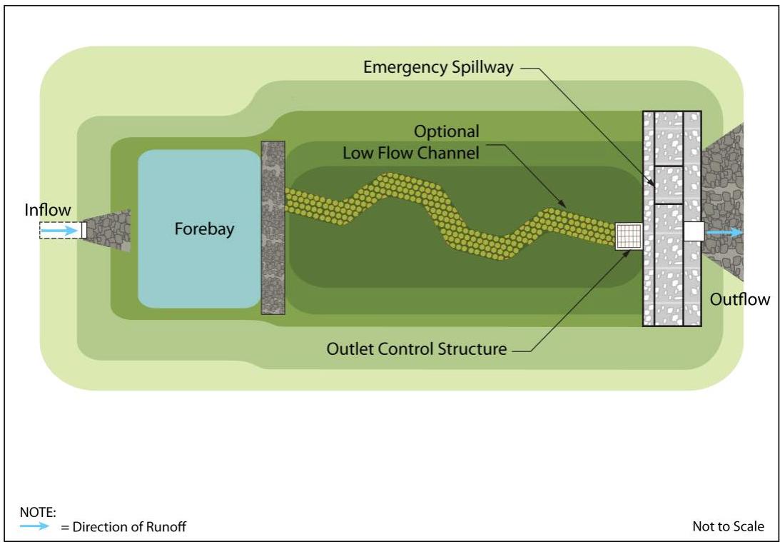
show a surface extended detention basin in both plan and profile views. The water surface elevation (W.S.E.) for the Water Quality Design Storm and the 2-, 10- and 100-year storms are individually labeled.

[OCR image]

[OCR image]
PDF page 7, image 2
Mistral ID: img-6.jpeg. Extraction bundle(s): 2026_BMP_11_2_Extended_Detention_Basins. Original page | Image file
Surrounding OCR excerpt:
tention basin in both plan and profile views. The water surface elevation (W.S.E.) for the Water Quality Design Storm and the 2-, 10- and 100-year storms are individually labeled.

[OCR image]

[OCR image]
PDF page 8, image 1
Mistral ID: img-7.jpeg. Extraction bundle(s): 2026_BMP_11_2_Extended_Detention_Basins. Original page | Image file
Surrounding OCR excerpt:
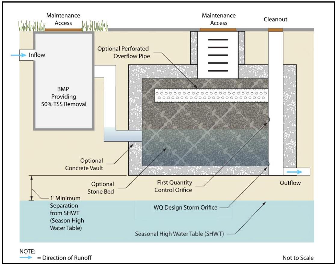
to installation. For additional information, see the discussion of pretreatment found on Page 12. The illustration below shows an example of a stone-filled vault type of subsurface extended detention basin.

[OCR image]

Any roof runoff may be pretreated by leaf screens, first flush diverters or roof washers. For details of these pretreatment measures, see Pages 5 and 6 of Chapter 9.1: Cisterns.

- This pretreatment requirement for roof runoff can be waived by the review agency if the building in question has no potential for debris and other vegetative material to be present in the roof runoff. For example, a building
PDF page 9, image 1
Mistral ID: img-8.jpeg. Extraction bundle(s): 2026_BMP_11_2_Extended_Detention_Basins. Original page | Image file
Surrounding OCR excerpt:
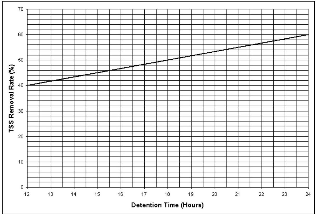
detention times in excess of 24 hours will still only be credited with a 60% TSS removal rate. Extrapolation beyond the minimum and maximum detention times of 12 and 24 hours, respectively, is not allowed.

[OCR image]

To determine the TSS removal rate for an extended detention basin, either the chart above or the following equation may be used:

$$
\% \text{TSS Removal Rate} = 40 + \left\{20 \times \left\lfloor \frac{t - 12}{12} \right\rfloor \right\}
$$

where $t$ is the time of detention in hours and $12 \leq t \leq 24$.

The example located on the following page illustrates how to use the chart to determine the T
PDF page 11, image 1
Mistral ID: img-9.jpeg. Extraction bundle(s): 2026_BMP_11_2_Extended_Detention_Basins. Original page | Image file
Surrounding OCR excerpt:
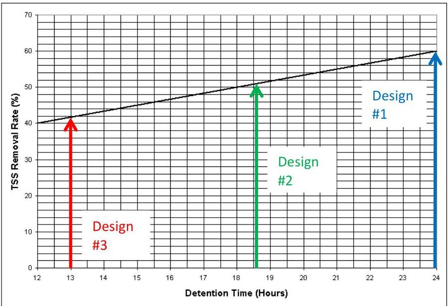
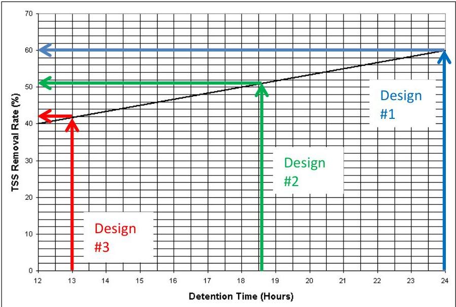
Step 4: For each of the designs, find the respective detention time along the horizontal axis of the chart found on Page 9 and draw a vertical line up to the curve on the chart.

[OCR image]

Step 5: For each design, next draw a horizontal line from the point on the curve identified in Step #4 to the vertical axis to obtain the corresponding TSS Removal Rate.

[OCR image]

The resulting percent TSS Removal Rates appear in the last column of the table provided on the next page.
PDF page 11, image 2
Mistral ID: img-10.jpeg. Extraction bundle(s): 2026_BMP_11_2_Extended_Detention_Basins. Original page | Image file
Surrounding OCR excerpt:
chart.

[OCR image]

Step 5: For each design, next draw a horizontal line from the point on the curve identified in Step #4 to the vertical axis to obtain the corresponding TSS Removal Rate.

[OCR image]

The resulting percent TSS Removal Rates appear in the last column of the table provided on the next page.