Extracted images: Wet Ponds Non-GI
Printed revision: January 2026.
Back to source | Original PDF | Image metadata
Original Mistral crops are preserved byte for byte. A crop can be a figure, table, equation, or other visual; no visual content is inferred as a numerical rule. Record and table associations use the same PDF page unless a direct image placeholder is identified. Nearby OCR excerpts are context, not verified captions.
PDF page 1, image 1
Mistral ID: img-0.jpeg. Extraction bundle(s): 2026_BMP_11_6_Wet_Ponds_Non_GI. Original page | Image file
Tables on the same PDF page: Table 1
Surrounding OCR excerpt:
# 11.6 WET PONDS (NON-GI)

[OCR image]

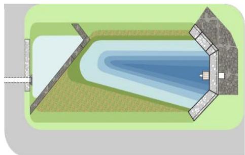
Wet ponds, also known as retention basins, have an elevated outlet structure that creates a permanent pool where stormwater runoff is detained and attenuated. Wet ponds can be designed as multi-stage, multi-function systems; extended detention in the permanent pool provides pollutant treatment for runoff from the Water Quality Design Storm through sedimentation and biological processing; detention and
PDF page 2, image 1
Mistral ID: img-1.jpeg. Extraction bundle(s): 2026_BMP_11_6_Wet_Ponds_Non_GI. Original page | Image file

Surrounding OCR excerpt:
the definition of green infrastructure.

Wet ponds must have a maintenance plan and must be reflected in a deed notice recorded in the county clerk's office to prevent alteration or removal.

# Applications

[OCR image]

Only if a waiver or variance from the green infrastructure requirements of N.J.A.C. 7:8-5.3 is obtained may wet ponds that are designed as an on-line system be used to meet the stormwater runoff quantity requirements. Additionally, regardless of the design storm chosen, wet ponds must be designed for stability in accordance with the Standards for Soil Erosion and Sediment Control in New Jersey, as requ
PDF page 5, image 1
Mistral ID: img-2.jpeg. Extraction bundle(s): 2026_BMP_11_6_Wet_Ponds_Non_GI. Original page | Image file
Surrounding OCR excerpt:
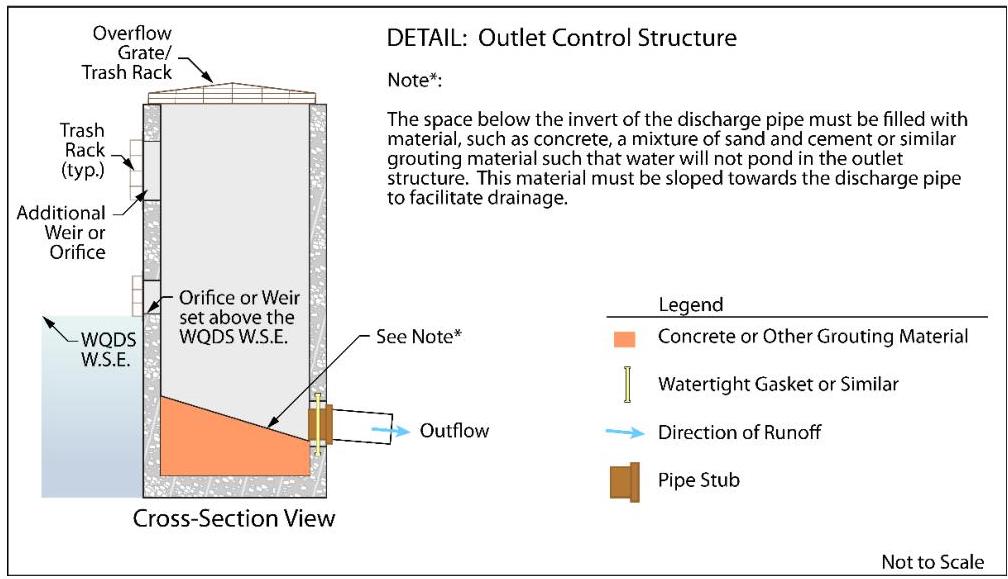
$\square$  Constructed of rigid, durable and corrosion-resistant material; and
Designed to withstand a perpendicular live loading of 300 lbs./sf.

[OCR image]

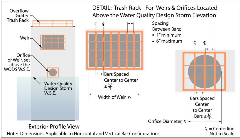
- An overflow grate is designed to prevent obstruction of the overflow structure. If an outlet structure has an overflow grate, the grate must comply with the following requirements:

☐ The overflow grate must be secured to the outlet structure but removable for emergencies and maintenance;
☐ The overflow grate spacing must be no greater than 2 inches across the smallest dimension; and
☐ The overflow g
PDF page 6, image 1
Mistral ID: img-3.jpeg. Extraction bundle(s): 2026_BMP_11_6_Wet_Ponds_Non_GI. Original page | Image file
Surrounding OCR excerpt:
[OCR image]

- All wet ponds must be designed to safely convey overflows to downstream drainage systems. The design of the overflow structure must be sufficient to provide safe, stable discharge of stormwater in the event of an overflow. Safe and stable discharge minimizes the possibility of erosion and flooding in down-gradient areas. Therefore, discharge in the event of an overflow must be consistent with the cur
PDF page 8, image 1
Mistral ID: img-4.jpeg. Extraction bundle(s): 2026_BMP_11_6_Wet_Ponds_Non_GI. Original page | Image file
Surrounding OCR excerpt:
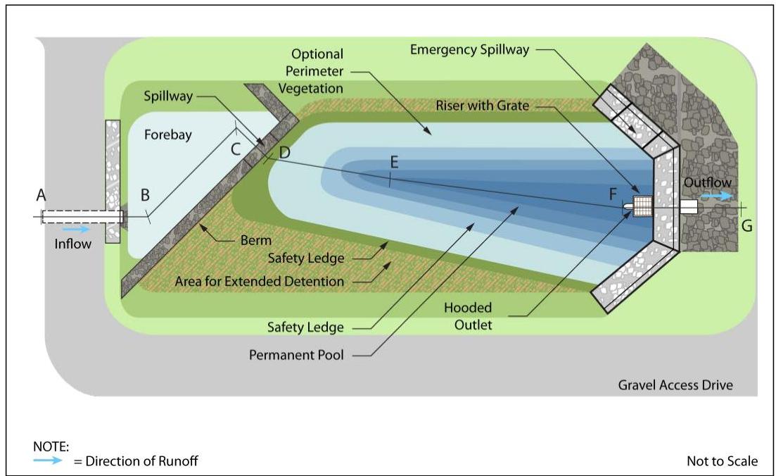
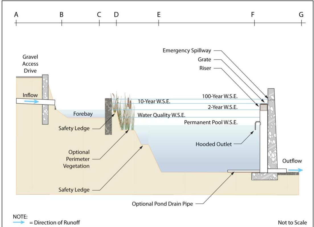
ents comprising a wet pond in both plan and profile view. The lettered path shown in the plan view represents the alignment along which an imaginary slice was made to prepare the corresponding profile view.

[OCR image]
Wet Pond - Plan View

[OCR image]
Wet Pond - Profile View
PDF page 8, image 2
Mistral ID: img-5.jpeg. Extraction bundle(s): 2026_BMP_11_6_Wet_Ponds_Non_GI. Original page | Image file
Surrounding OCR excerpt:
ile view. The lettered path shown in the plan view represents the alignment along which an imaginary slice was made to prepare the corresponding profile view.

[OCR image]
Wet Pond - Plan View

[OCR image]
Wet Pond - Profile View
PDF page 9, image 1
Mistral ID: img-6.jpeg. Extraction bundle(s): 2026_BMP_11_6_Wet_Ponds_Non_GI. Original page | Image file
Surrounding OCR excerpt:
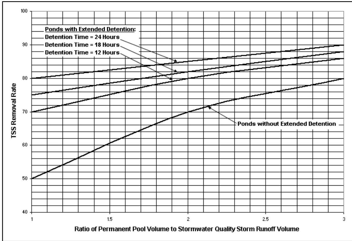
wet pond is 90%; to achieve this TSS removal rate, the system must be designed with 24-hours of extended detention and a 3:1 ratio of permanent pool volume to the volume of stormwater generated by the WQDS.

[OCR image]

The following example illustrates how to use the chart to determine the TSS removal rate provided.
PDF page 10, image 1
Mistral ID: img-7.jpeg. Extraction bundle(s): 2026_BMP_11_6_Wet_Ponds_Non_GI. Original page | Image file
Tables on the same PDF page: Table 2 | Table 3
Surrounding OCR excerpt:
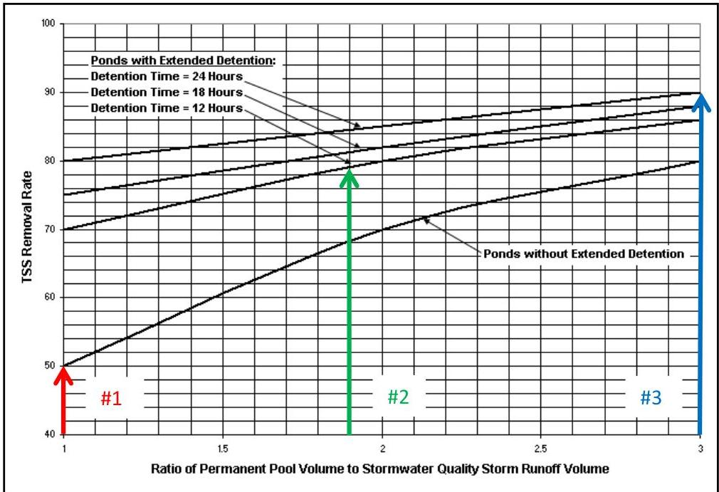
ides. Design #1 provides no extended detention; therefore, the lowest curve is used to determine the TSS removal rate. Designs #2 and 3 provide extended detention and therefore, use the upper set of curves.

[OCR image]
PDF page 11, image 1
Mistral ID: img-8.jpeg. Extraction bundle(s): 2026_BMP_11_6_Wet_Ponds_Non_GI. Original page | Image file
Tables on the same PDF page: Table 4
Surrounding OCR excerpt:
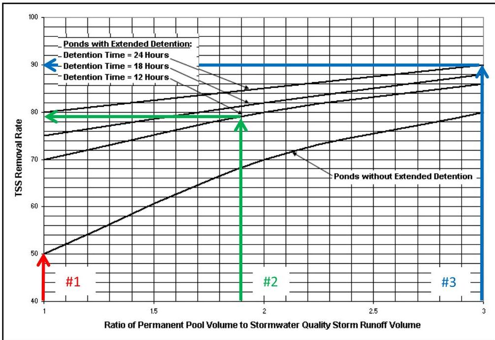
Step 3: For each of the designs, at the intersection of the vertical line from Step 2 with the respective curve, draw a horizontal line from right to left over to the y-axis to get the TSS removal rate.

[OCR image]

The resulting percent TSS Removal Rates appear in the last column of the table below.

|  Design Number | Permanent Pool Volume (ac-ft) | WQ Runoff Volume | Extended Detention Period |   |   | Ratio of Permanent Pool to WQ Runoff | % TSS Removal  |
| --- | --- | --- | --- | --- | --- | --- | --- |
|   |   |   |  12 Hr | 18 Hr | 24 Hr  |   |   |
|  1 | 1.246 | 1.246 | - | - | - | 1.0 | 50%  |
|  2 | 2.7