Extracted images: Soil Testing Criteria
Printed revision: March 2024.
Back to source | Original PDF | Image metadata
Original Mistral crops are preserved byte for byte. A crop can be a figure, table, equation, or other visual; no visual content is inferred as a numerical rule. Record and table associations use the same PDF page unless a direct image placeholder is identified. Nearby OCR excerpts are context, not verified captions.
PDF page 4, image 1
Mistral ID: img-0.jpeg. Extraction bundle(s): 2026_BMP_12_Soil_Testing_Criteria. Original page | Image file
Surrounding OCR excerpt:
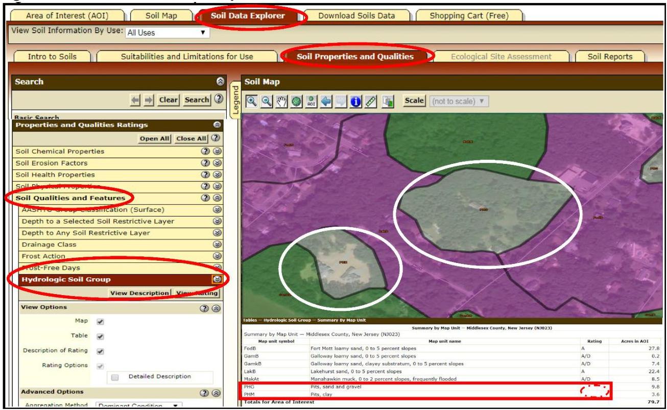
b "Soil Properties and Qualities," and under the drop-down menu "Soil Qualities and Features," followed by "Hydrologic Soil Group" shown in Figure 12-1a, each of which are circled in red in the image below.

[OCR image]
Figure 12-1a: NRCS Web Soil Survey
PDF page 6, image 1
Mistral ID: img-1.jpeg. Extraction bundle(s): 2026_BMP_12_Soil_Testing_Criteria. Original page | Image file
Tables on the same PDF page: Table 12-2: Default Soil Series for NJGRS Recharge Computation
Surrounding OCR excerpt:
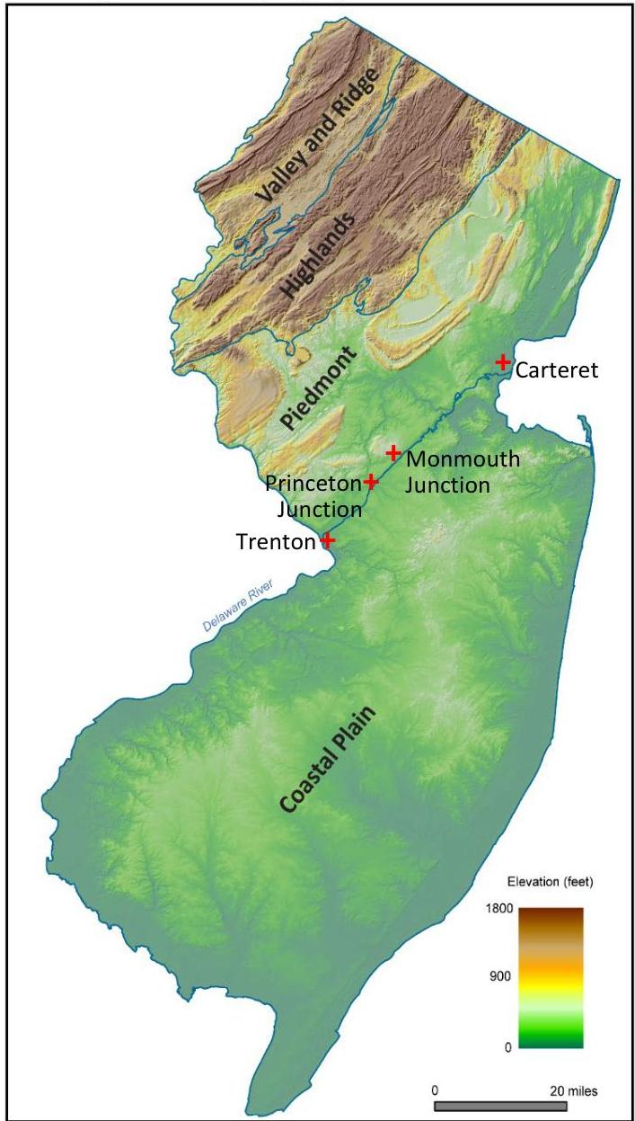
Figure 12-2: Physiographic Provinces of NJ
[OCR image]
Image modified from the New Jersey Geological Survey Information Circular, "Physiographic Provinces of New Jersey, 2006" and used with permission.

Table 12-2: Default Soil Series for NJGRS Recharge Computation

|  HSG | Soil Series Name  |
| --- | --- |
|  A | Fort Mott  |
|  B | Nixon  |
|  C | Readington  |
|  D | Any soil series that results in zero annual recharge  |
PDF page 17, image 1
Mistral ID: img-2.jpeg. Extraction bundle(s): 2026_BMP_12_Soil_Testing_Criteria. Original page | Image file
Surrounding OCR excerpt:
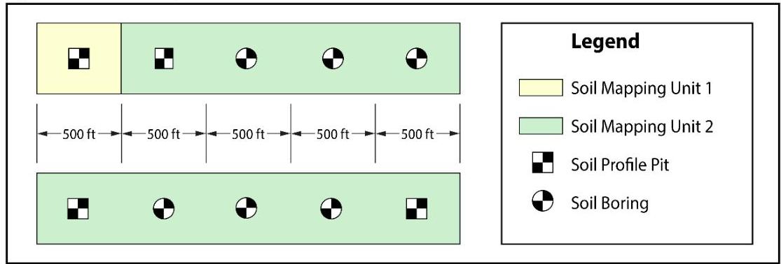
linear BMP. Take note that soil profile pits from different soil mapping units may be more distant from each other in order to obtain more information about the geomorphology characteristics of the project.

[OCR image]
Figure 12-4: Soil Exploration Locations for Linear Infiltration BMPs

## 5. Allowable substitutions

A soil profile pit may be substituted by soil borings only when the conditions stated in the subsection titled “Soil Boring and Profile Pit Locations and Allowable Substitutions,” which begins on Page 7, are fully met.

## 6. Proximity of soil exploration(s) to the actual location of a BMP

The final loc
PDF page 24, image 1
Mistral ID: img-3.jpeg. Extraction bundle(s): 2026_BMP_12_Soil_Testing_Criteria. Original page | Image file
Surrounding OCR excerpt:
[OCR image]
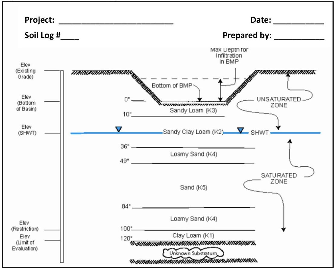
Figure 12-6: Sample Soil Log (For Direct Observation of SHWT)

On Page 25, Figure 12-7 depicts a soil profile cross-section example obtained from the Pinelands Commission, which is available online at:

https://www.state.nj.us/pinelands/appli/tools/new%20forms/Pinelands%20Stormwater%20BMP%20Cross%20Section%20Design%20Example.pdf.

On Page 26, Figure 12-8 depicts an example of an Excel spreadsheet create
PDF page 25, image 1
Mistral ID: img-4.jpeg. Extraction bundle(s): 2026_BMP_12_Soil_Testing_Criteria. Original page | Image file
Tables on the same PDF page: Table 17
Surrounding OCR excerpt:
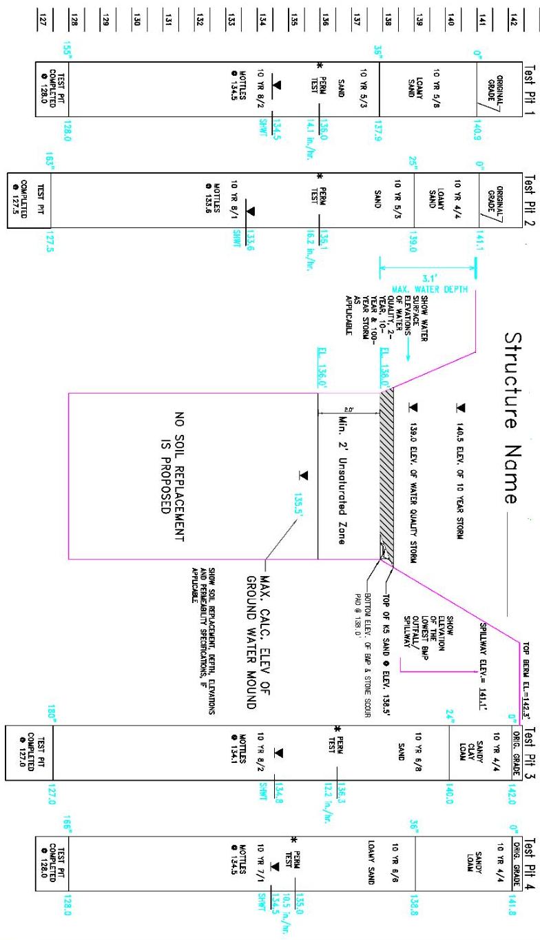
Figure 12-7: Pineland Commission Soil Cross-Section Design Example
[OCR image]
- SHOW ORIGINAL GROUND SURFACE ELEVATION AT EACH TEST PIT LOCATION.
- SHOW DEPTH AND ELEVATION OF EACH HORIZON BOUNDARY IN TEST PIT LOGS.
- SHOW TEXTURE & MONOEL COLORS) OF EACH HORIZON IN TEST PIT LOGS.
- SHOW ELEVATION OF SEASONAL HIGH WATER LEVEL IN EACH TEST PIT LOC.

# NOTES:

1) HIGHEST SHWT ELEVATION = 134.8
2) MAXIMUM CALC. GROUND WATER MOUND
C.F.V. = 535.5
3) LOWEST ELEVATION (INVERT) OF BM
PDF page 32, image 1
Mistral ID: img-5.jpeg. Extraction bundle(s): 2026_BMP_12_Soil_Testing_Criteria. Original page | Image file
Surrounding OCR excerpt:
in frozen ground or in holes which have been allowed to remain open to the atmosphere for periods greater than three days.
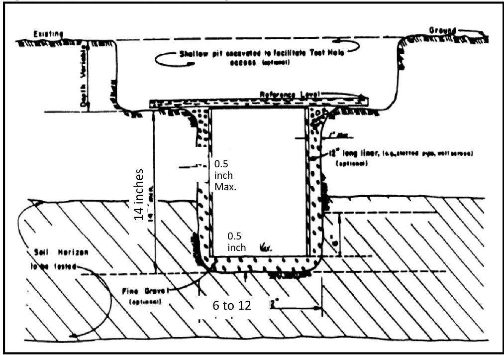
- The required configuration of the test hole is illustrated in Figure 12-9, below.

[OCR image]
Figure 12-9: Percolation Test Configuration

# 1. Equipment Requirements

The following equipment is required for the percolation test:

a. A soil auger, post-hole digger or other means of preparing a test hole as prescribed below,
b. A knife or trowel for removing smeared or compacted surfaces from the walls of the test hole,
c. Fine (from 2 to 10 millimeter in diameter) gravel (optional),
d. A water s
PDF page 37, image 1
Mistral ID: img-6.jpeg. Extraction bundle(s): 2026_BMP_12_Soil_Testing_Criteria. Original page | Image file
Surrounding OCR excerpt:
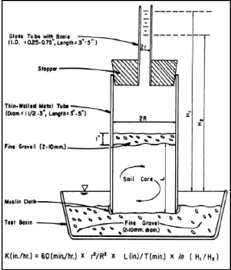
w) can be utilized to establish the soil hydraulic conductivity in accordance with the procedures below. Take note: the tube permeameter test can only be used only when undisturbed samples can be collected.

[OCR image]
Figure 12-11: Tube Permeameter (with Standpipe)

1. Equipment Requirements

The following equipment is required for performing a tube permeameter test:

a. A thin-walled (1 millimeter or less in thickness) metal tube, from 1.5 to 3 inches in diameter, 6 inches in length and beveled on the lower outside edge,
b. A wooden block with dimensions broader than the diameter of the tube in the previous item abo
PDF page 47, image 1
Mistral ID: img-7.jpeg. Extraction bundle(s): 2026_BMP_12_Soil_Testing_Criteria. Original page | Image file
Surrounding OCR excerpt:
ted in frozen ground nor in holes which have been allowed to remain open to the atmosphere for periods greater than three days.
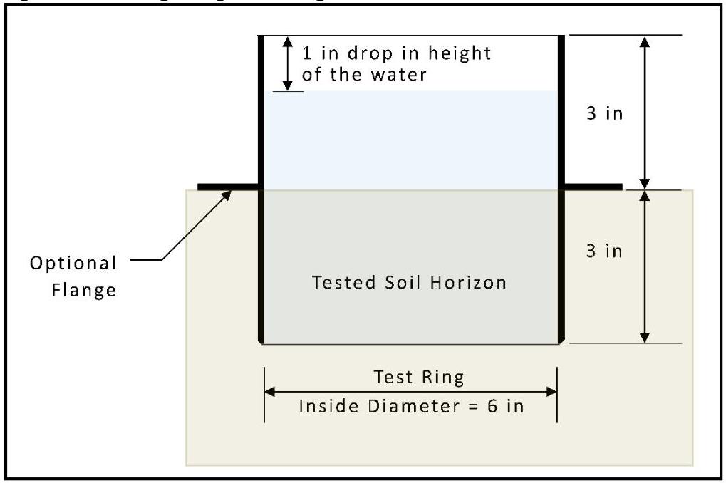
- The required configuration of the test is illustrated in Figure 12-12 below.

[OCR image]
Figure 12-12: Single ring test configuration

## 1. Equipment Requirements

The following equipment is required for the Single Ring Infiltration test:

a. A 6 inch long beveled edge test ring with an inside diameter of 6 inches,

i. It is better if the test ring has an outer flange located 3 inches from the lower end of the test ring in order to stop the test ring from penetrating more than 3 inches int
PDF page 50, image 1
Mistral ID: img-8.jpeg. Extraction bundle(s): 2026_BMP_12_Soil_Testing_Criteria. Original page | Image file
Surrounding OCR excerpt:
[OCR image]

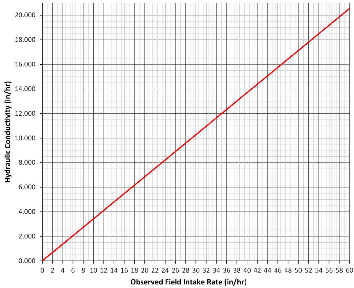
When the observed field intake rate is greater than 60 in/hr, the hydraulic conductivity shall be reported as "greater than 20 in/hr." When the observed field intake rate is less than 1 in/hr, the hydraulic conductivity shall be reported as "less than 1 in/hr."

## 5. Reporting the test results

The information in the test report shall include, at a minimum, the following items:

a. Date and time,
b. P