Extracted images: Volumetric Reduction Standards
Printed revision: January 2026.
Back to source | Original PDF | Image metadata
Original Mistral crops are preserved byte for byte. A crop can be a figure, table, equation, or other visual; no visual content is inferred as a numerical rule. Record and table associations use the same PDF page unless a direct image placeholder is identified. Nearby OCR excerpts are context, not verified captions.
PDF page 6, image 1
Mistral ID: img-0.jpeg. Extraction bundle(s): 2026_BMP_14_Volumetric_Reductions_Standards. Original page | Image file
Surrounding OCR excerpt:
[OCR image]
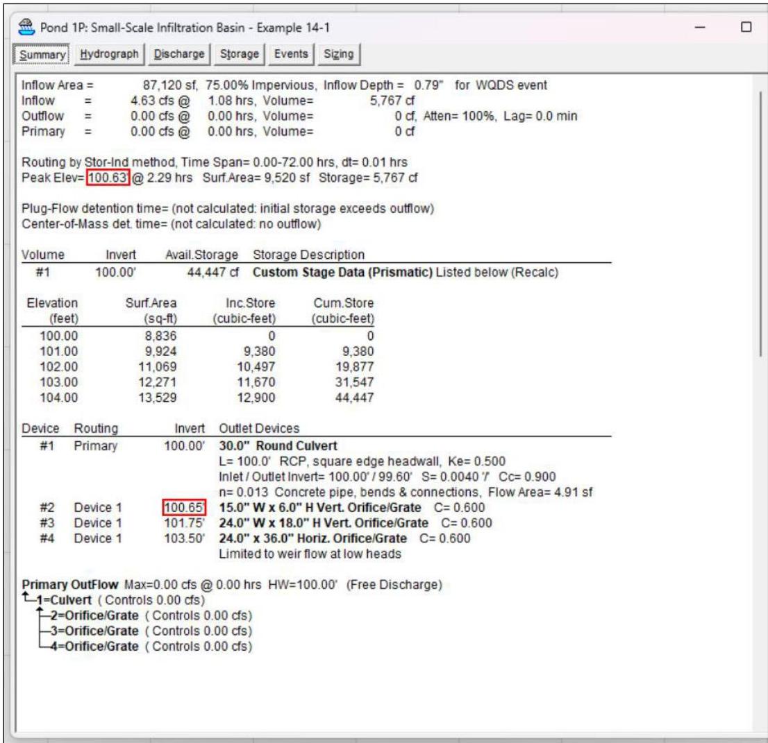
Source: HydroCAD® Summary Report; HydroCAD is a registered trademark of HydroCAD Software Solutions LLC. Used with permission.

# Example 14-2: Use of an Underdrained Small-Scale Bioretention System to Meet N.J.A.C. 7:5-6(d)1i(1) and (2)

A 2-acre wooded area in Morris County is to be developed. The site is on HSG 'C' soil. The proposed development will consist of 0.75 acres of building area, 0.5 acres
PDF page 7, image 1
Mistral ID: img-1.jpeg. Extraction bundle(s): 2026_BMP_14_Volumetric_Reductions_Standards. Original page | Image file
Surrounding OCR excerpt:
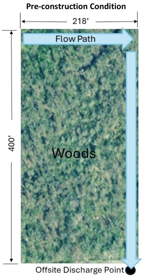
ruction condition will flow toward the right boundary of the site and then flow down to the south corner of the site before the runoff leaves the site.

Conceptual layouts of the site are illustrated below.

[OCR image]

[OCR image]

The models and calculations presented below show the design for the volumetric reduction standards only. For the design to meet stormwater water quantity, quality and groundwater recharge standards, Chapters 5, 6 and 9.7 of the BMP Manual provide detailed calculations and examples.

# Step 1: Identify the disturbed area subject to the volumetric reduction standards

In accord
PDF page 7, image 2
Mistral ID: img-2.jpeg. Extraction bundle(s): 2026_BMP_14_Volumetric_Reductions_Standards. Original page | Image file
Surrounding OCR excerpt:
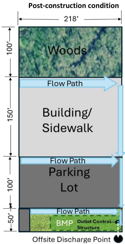
toward the right boundary of the site and then flow down to the south corner of the site before the runoff leaves the site.

Conceptual layouts of the site are illustrated below.

[OCR image]

[OCR image]

The models and calculations presented below show the design for the volumetric reduction standards only. For the design to meet stormwater water quantity, quality and groundwater recharge standards, Chapters 5, 6 and 9.7 of the BMP Manual provide detailed calculations and examples.

# Step 1: Identify the disturbed area subject to the volumetric reduction standards

In accordance with N.J.A.C. 7:8-5.6(
PDF page 8, image 1
Mistral ID: img-3.jpeg. Extraction bundle(s): 2026_BMP_14_Volumetric_Reductions_Standards. Original page | Image file
Surrounding OCR excerpt:
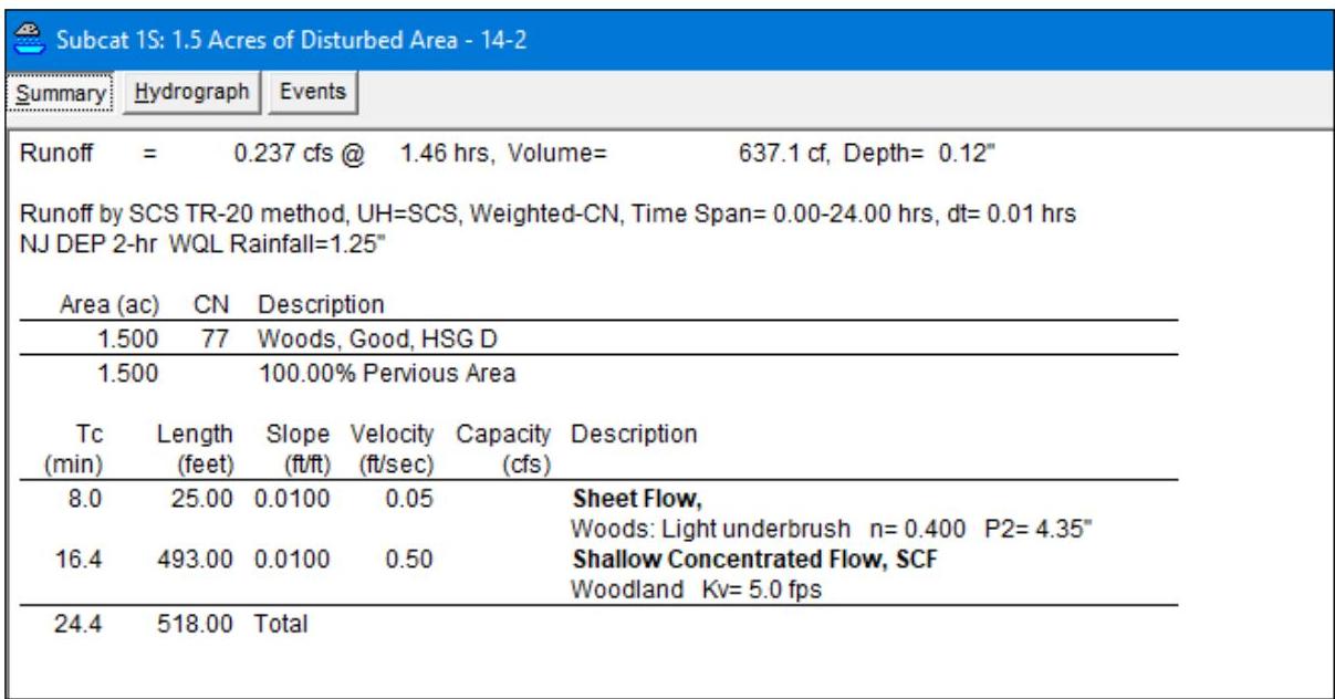
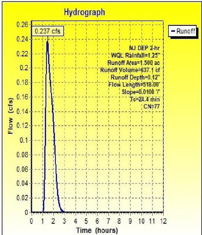
d hydraulic model for the 1.5-acre woods is shown below. The peak flow rate is 0.237 cfs. The hydrograph starts at 1.10 hours and ends at 3.0 hours. As a result, the runoff hydrograph duration is 1.9 hours.

[OCR image]
Source: HydroCAD® Summary Report; HydroCAD is a registered trademark of HydroCAD Software Solutions LLC. Used with permission.
PDF page 9, image 1
Mistral ID: img-4.jpeg. Extraction bundle(s): 2026_BMP_14_Volumetric_Reductions_Standards. Original page | Image file
Tables on the same PDF page: Table 1
Surrounding OCR excerpt:
[OCR image]
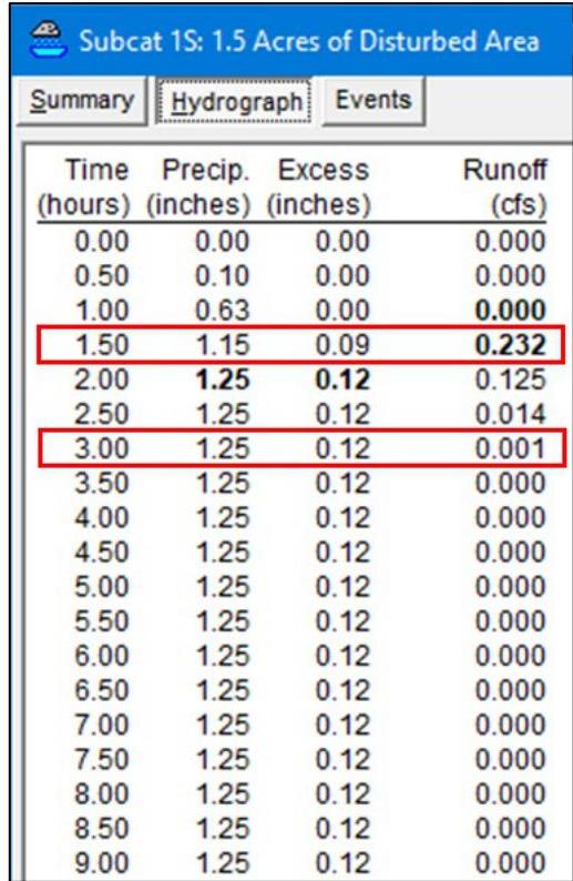
Source: HydroCAD® Hydrograph Graph and Tabular Report; HydroCAD is a registered trademark of HydroCAD Software Solutions LLC. Used with permission.

[OCR image]

# Step 3: Hydrologic and hydraulic analysis for the post-construction condition

The parameters of the hydrologic and hydraulic models for the buidling, parking lot and the lawn area are shown below:

|  Land Cover | CN | Sheet Fl
PDF page 9, image 2
Mistral ID: img-5.jpeg. Extraction bundle(s): 2026_BMP_14_Volumetric_Reductions_Standards. Original page | Image file
Tables on the same PDF page: Table 1
Surrounding OCR excerpt:
[OCR image]
Source: HydroCAD® Hydrograph Graph and Tabular Report; HydroCAD is a registered trademark of HydroCAD Software Solutions LLC. Used with permission.

[OCR image]

# Step 3: Hydrologic and hydraulic analysis for the post-construction condition

The parameters of the hydrologic and hydraulic models for the buidling, parking lot and the lawn area are shown below:

|  Land Cover | CN | Sheet Flow Length (ft) | Shallow Concentrated Flow Length (ft) | Mannings's n | Slope  |
| --- | --- | --- | --- | --- | --- |
|  Building | 98 | 100 | 268 | 0.011 | 1%  |
|  Parking
PDF page 10, image 1
Mistral ID: img-6.jpeg. Extraction bundle(s): 2026_BMP_14_Volumetric_Reductions_Standards. Original page | Image file
Surrounding OCR excerpt:
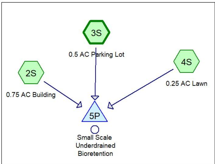
and performance standards at N.J.A.C. 7:8-5.4, 5.5, and 5.6. The outlet and underdrain configurations shown in the model below are for example purposes only. Design engineers may have other configurations.

[OCR image]
Source: HydroCAD® Diagram; HydroCAD is a registered trademark of HydroCAD Software Solutions LLC. Used with permission. Each numbered element is called a "node."
PDF page 12, image 1
Mistral ID: img-7.jpeg. Extraction bundle(s): 2026_BMP_14_Volumetric_Reductions_Standards. Original page | Image file
Tables on the same PDF page: Table 3
Surrounding OCR excerpt:
[OCR image]
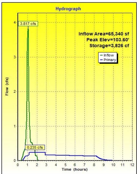
Source: HydroCAD® Hydrograph Graph and Tabular Report; HydroCAD is a registered trademark of HydroCAD Software Solutions LLC. Used with permission.

|  Time (hours) | Inflow (cfs) | Storage (cubic-feet) | Elevation (feet) | Primary (cfs)  |
| --- | --- | --- | --- | --- |
|  0.00 | 0.000 | 0 | 100.00 | 0.000  |
|  0.50 | 0.120 | 32 | 100.01 | 0.018  |
|  1.00 | 3.340 | 1,111 | 100.37 | 0.140  |
|  1.50