Extracted images: Infiltration Basins (Large-Scale GI)
Printed revision: January 2026.
Back to source | Original PDF | Image metadata
Original Mistral crops are preserved byte for byte. A crop can be a figure, table, equation, or other visual; no visual content is inferred as a numerical rule. Record and table associations use the same PDF page unless a direct image placeholder is identified. Nearby OCR excerpts are context, not verified captions.
PDF page 1, image 1
Mistral ID: img-0.jpeg. Extraction bundle(s): 2026_BMP_10_2_Infiltration_Basins. Original page | Image file
Tables on the same PDF page: Table 1
Surrounding OCR excerpt:
# 10.2 INFILTRATION BASINS (LARGE-SCALE)

[OCR image]

Infiltration basins are stormwater management systems constructed with highly permeable components designed to both maximize the removal of pollutants from stormwater, promote groundwater recharge and address the quantity impacts of land development. Pollutants are treated through settling, filtration of the runoff through, and biological and chemical activity within, the components. The total suspende
PDF page 3, image 1
Mistral ID: img-1.jpeg. Extraction bundle(s): 2026_BMP_10_2_Infiltration_Basins. Original page | Image file

Surrounding OCR excerpt:
# Applications

The use of infiltration basins is applicable only where the soils have the required permeability rate identified in the Design Criteria section found below.

[OCR image]

Pursuant to N.J.A.C. 7:8-5.2(a)(2), the minimum design and performance standards for groundwater recharge, stormwater runoff quality and stormwater runoff quantity at N.J.A.C. 7:8- 5.4, 5.5 and 5.6 shall be met by incorporating green infrastructure in accordance with N.J.A.C. 7:8-5.3. Pursuant to N.J.A.C. 7:8-5.3(c), large-scale green infrastructure BMPs - i.e., those that exceed the contributory drain
PDF page 3, image 2
Mistral ID: img-2.jpeg. Extraction bundle(s): 2026_BMP_10_2_Infiltration_Basins. Original page | Image file

Surrounding OCR excerpt:
8-5.3(c), large-scale green infrastructure BMPs - i.e., those that exceed the contributory drainage area limits at N.J.A.C. 7:8-5.3(b) - may only be used to satisfy the stormwater runoff quantity standards.

[OCR image]

Infiltration basins may be designed to reduce peak runoff rates when designed as an online system in combination with a detention option; however, regardless of the design storm chosen, all infiltration basins must be designed for stability and in accordance with the Standards for Soil Erosion and Sediment Control in New Jersey.

[OCR image]

Only if a waiver or variance from the green in
PDF page 3, image 3
Mistral ID: img-3.jpeg. Extraction bundle(s): 2026_BMP_10_2_Infiltration_Basins. Original page | Image file

Surrounding OCR excerpt:
ntion option; however, regardless of the design storm chosen, all infiltration basins must be designed for stability and in accordance with the Standards for Soil Erosion and Sediment Control in New Jersey.

[OCR image]

Only if a waiver or variance from the green infrastructure requirements of N.J.A.C. 7:8-5.3 is obtained may infiltration basins that exceed the contributory drainage area limit of 5.3(b) be used to meet the groundwater recharge requirements.

[OCR image]

Only if a waiver or variance from the green infrastructure requirements of N.J.A.C. 7:8-5.3 is obtained may infiltration basins that ex
PDF page 3, image 4
Mistral ID: img-4.jpeg. Extraction bundle(s): 2026_BMP_10_2_Infiltration_Basins. Original page | Image file

Surrounding OCR excerpt:
he green infrastructure requirements of N.J.A.C. 7:8-5.3 is obtained may infiltration basins that exceed the contributory drainage area limit of 5.3(b) be used to meet the groundwater recharge requirements.

[OCR image]

Only if a waiver or variance from the green infrastructure requirements of N.J.A.C. 7:8-5.3 is obtained may infiltration basins that exceed the contributory drainage area limit of 5.3(b) be used to meet the stormwater runoff quality requirement.

# Design Criteria

## Basic Requirements

An infiltration basin may be designed as a surface or subsurface system. The following criteria apply to both config
PDF page 5, image 1
Mistral ID: img-5.jpeg. Extraction bundle(s): 2026_BMP_10_2_Infiltration_Basins. Original page | Image file
Surrounding OCR excerpt:
ly affect the hydraulic performance of the outlet pipe or structure;
☐ Constructed of rigid, durable and corrosion-resistant material; and
☐ Designed to withstand a perpendicular live loading of 300 lbs/sf.

[OCR image]

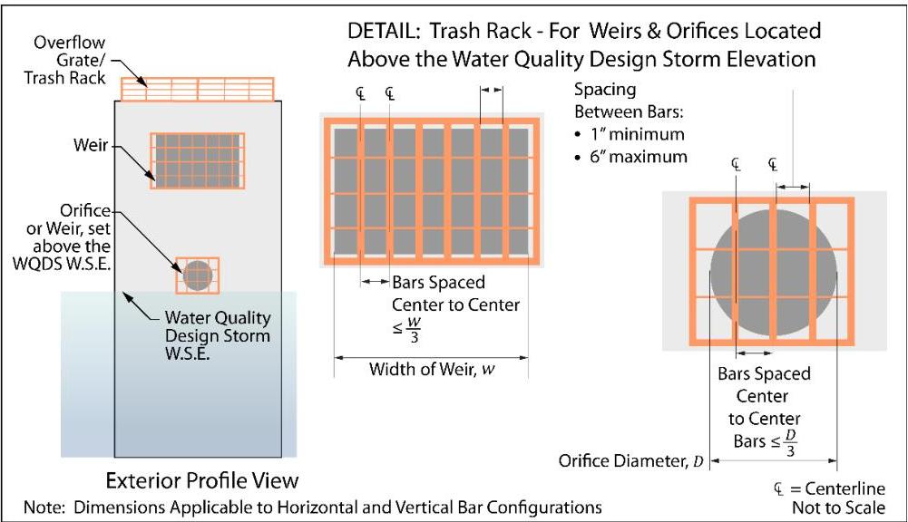
- An overflow grate is designed to prevent obstruction of the overflow structure. If an outlet structure has an overflow grate, the grate must comply with the following requirements:

☐ The overflow grate must be secured to the outlet structure but removable for emergencies and maintenance;
☐ The overflow grate spacing must be no greater than 2 inches across the smallest dimension; and
☐ The overflow g
PDF page 6, image 1
Mistral ID: img-6.jpeg. Extraction bundle(s): 2026_BMP_10_2_Infiltration_Basins. Original page | Image file
Surrounding OCR excerpt:
[OCR image]

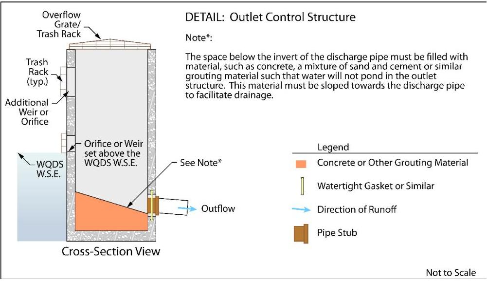
- Any flow control device, such as an orifice, weir, grate or perforated pipe, at the outlet of the stormwater management measures shall be designed to prevent the clogging of the flow control device while achieving the design and performance standards at N.J.A.C. 7:8-5.4, 5.5 and 5.6.
- Blind connections to down-gradient facilities are prohibited. Any connection to down-gradient stormwater management
PDF page 8, image 1
Mistral ID: img-7.jpeg. Extraction bundle(s): 2026_BMP_10_2_Infiltration_Basins. Original page | Image file
Surrounding OCR excerpt:
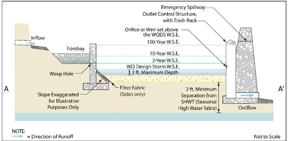
urface elevation of the 2-, 10-, and 100-year storm events. To prevent the accumulation of runoff from exceeding the 2 foot maximum depth limit, an orifice is set at the water surface elevation of the WQDS.

[OCR image]
PDF page 9, image 1
Mistral ID: img-8.jpeg. Extraction bundle(s): 2026_BMP_10_2_Infiltration_Basins. Original page | Image file
Surrounding OCR excerpt:
# Infiltration Basin with the Detention Option: Profile View

[OCR image]

## Types of Infiltration Basins

There are two types of infiltration basins:

1. Surface Infiltration Basins
2. Subsurface Infiltration Basins

## Individual Types of Infiltration Basins

The following section provides detailed design criteria for each type of infiltration basin. The illustrations depict possible configurations and flow paths and are not intended to limit the design.

## Surface Infilt
PDF page 10, image 1
Mistral ID: img-9.jpeg. Extraction bundle(s): 2026_BMP_10_2_Infiltration_Basins. Original page | Image file
Surrounding OCR excerpt:
eability.

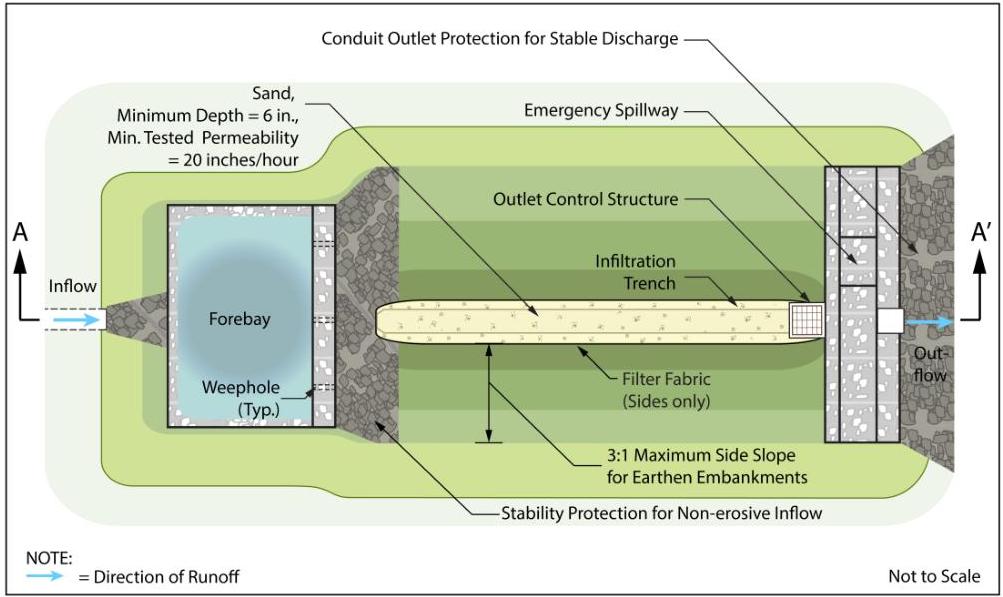
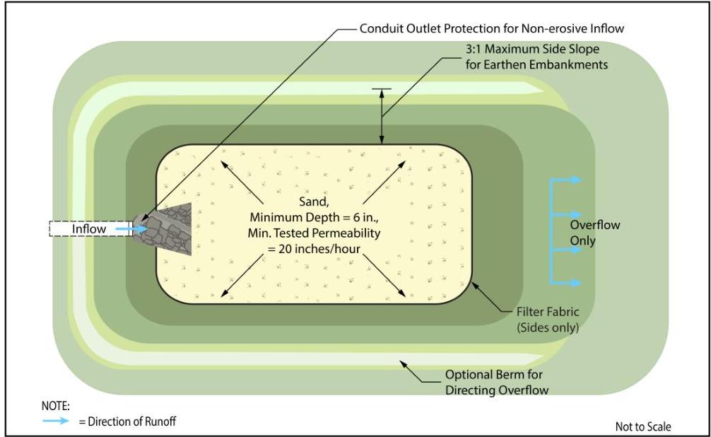
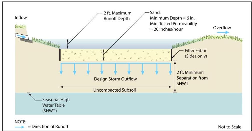
The following graphics depict a surface infiltration basin in both plan and profile view. These illustrations show possible configurations and flow paths and are not intended to limit the design.

[OCR image]
Surface Infiltration Basin – Plan View

[OCR image]
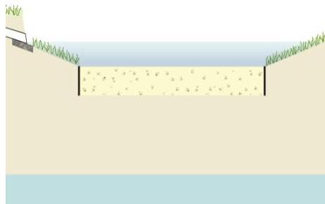
Surface Infiltration Basin – Profile View
PDF page 10, image 2
Mistral ID: img-10.jpeg. Extraction bundle(s): 2026_BMP_10_2_Infiltration_Basins. Original page | Image file
Surrounding OCR excerpt:
in in both plan and profile view. These illustrations show possible configurations and flow paths and are not intended to limit the design.

[OCR image]
Surface Infiltration Basin – Plan View

[OCR image]
Surface Infiltration Basin – Profile View
PDF page 11, image 1
Mistral ID: img-11.jpeg. Extraction bundle(s): 2026_BMP_10_2_Infiltration_Basins. Original page | Image file
Surrounding OCR excerpt:
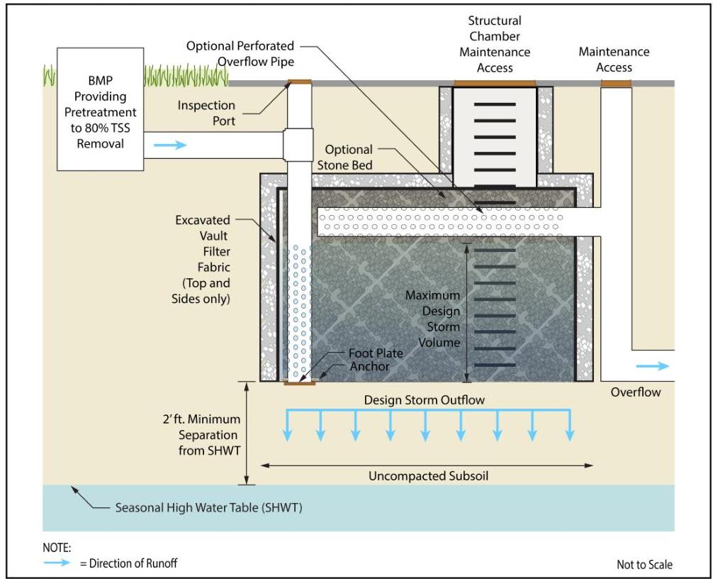
s a vault is depicted in the following illustration as an example, but it is not intended to limit the design configuration. Design criteria specific to this type of infiltration basin immediately follows.

[OCR image]

## Subsurface Infiltration Basin – Profile View

### Pretreatment for Subsurface Infiltration Basins

- Pretreatment is required on all subsurface infiltration basins.
- Roof runoff that directly discharges into the subsurface infiltration basin can be pretreated by leaf screens, first flush diverters or roof washers. For details of these pretreatment measures, see Pages 5 and 6 of Chapter 9.1: Cister
PDF page 14, image 1
Mistral ID: img-12.jpeg. Extraction bundle(s): 2026_BMP_10_2_Infiltration_Basins. Original page | Image file
Surrounding OCR excerpt:
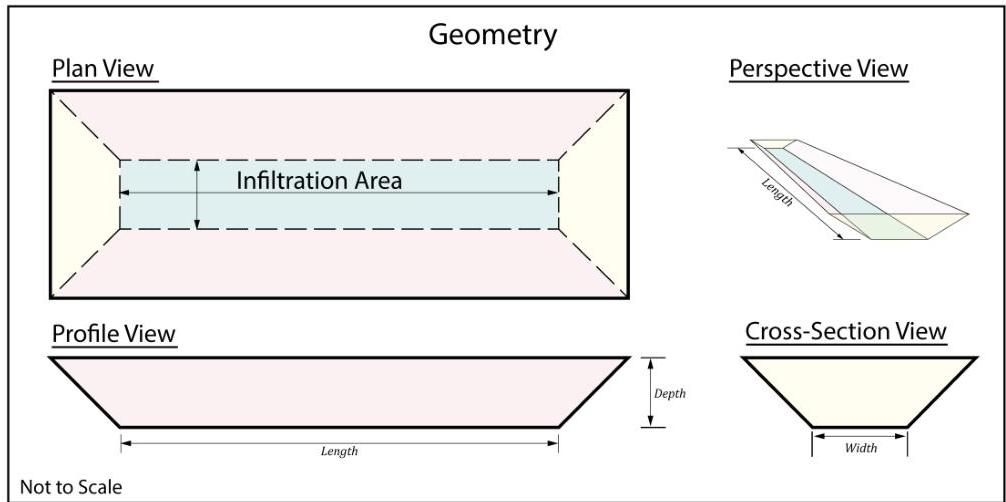
depth and side slopes. A footprint of 45 ft wide and 80.04 ft long is designed. A side slope 3:1 (horizontal to vertical) is configured, which results in 92.04 ft long and 57 ft wide at the height of 2 ft.

[OCR image]
Example 1 - Geometry
Step 4: Estimated Drain Time Calculation

As previously stated, the drain time of the basin is determined by the design permeability rate of the subsoil. Note that only the infiltration area, i.e. the footprint, can be credited for infiltration, meaning infiltration may not be applied to the side slopes. The drain time calculation is based on the area of the footprint, which is 3,6
PDF page 15, image 1
Mistral ID: img-13.jpeg. Extraction bundle(s): 2026_BMP_10_2_Infiltration_Basins. Original page | Image file
Surrounding OCR excerpt:
[OCR image]
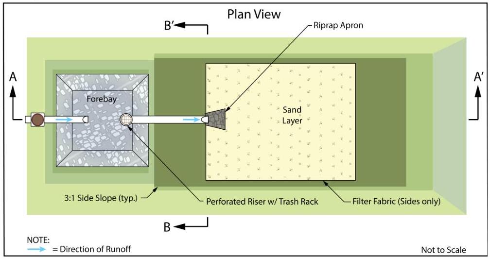
Example 1 - Plan View

[OCR image]
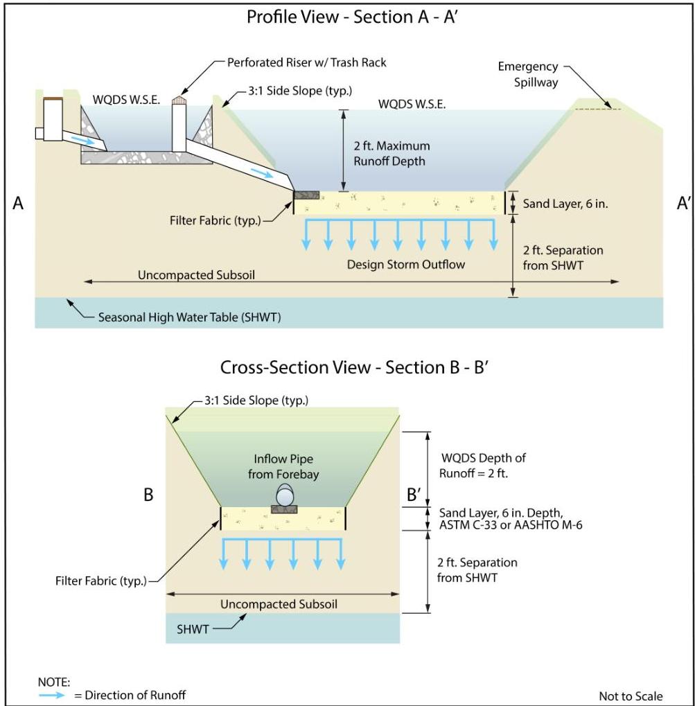
Example 1 - Profile and Cross-Section View
PDF page 15, image 2
Mistral ID: img-14.jpeg. Extraction bundle(s): 2026_BMP_10_2_Infiltration_Basins. Original page | Image file
Surrounding OCR excerpt:
[OCR image]
Example 1 - Plan View

[OCR image]
Example 1 - Profile and Cross-Section View